Continue to Site

Welcome to EDAboard.com

Welcome to our site! EDAboard.com is an international Electronics Discussion Forum focused on EDA software, circuits, schematics, books, theory, papers, asic, pld, 8051, DSP, Network, RF, Analog Design, PCB, Service Manuals... and a whole lot more! To participate you need to register. Registration is free. Click here to register now.

[SOLVED] [Moved] pwm using pic16f877a

Status
Not open for further replies.

Barun Sarkar

Newbie level 5
Joined
May 10, 2015
Messages
8
Helped
0
Reputation
0
Reaction score
0
Trophy points
1
Activity points
71
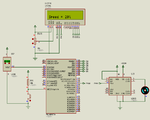
hi have used the code in proteus simulator and it works just fine but when i apply it the microprocessor does not give any out put. even the lcd does not display anything. please help.

View attachment pwm.txt


Code C - [expand]
1
2
3
4
5
6
7
8
9
10
11
12
13
14
15
16
17
18
19
20
21
22
23
24
25
26
27
28
29
30
31
32
33
34
35
36
37
38
39
40
41
42
43
44
45
46
47
48
49
50
51
52
53
54
55
56
57
58
59
60
61
62
63
64
65
66
67
68
69
70
71
72
73
74
75
76
77
78
79
80
81
82
83
84
85
86
87
88
89
90
91
92
93
94
95
96
97
98
99
100
101
102
103
104
105
#include<pic.h>
#include<math.h>
#include"lcd.h"
#include"delay.h" 
#include<stdio.h>
#define PWM_Freq 1 //1Khz PWM frequency 
#define TMR2_PRE 16 //Timer2 Prescale 
void main()     // main program begins
{
lcd_init();
unsigned  x,y,c=0x100,z;
float p,tmpr,f;
int j;
char a[5];
ADCON0=0;     //ADC channel-1 (AN0) is selected,A/D clock=Fosc/4 
TRISA=1;
ADCON1=0xCE;  //RA0 configured as ananlog (AN0),A/D result Right justified,A/D clock=Fosc/4
ADCON0=ADCON0|1;  //ADC is turned on
TRISC2=0; //PWM channel 1 and 2 configured as output 
TRISC1=0; 
PORTC = 0x00; 
CCP1CON=0x0c; //CCP1 and CCP2 are configured for PWM 
CCP2CON=0x0c; 
PR2=255; //Move the PR2 value 
T2CON=0x03; //Timer2 Prescale is 16 
TMR2=0x00; 
TMR2ON=1; //Turn ON timer2 
CCPR1L=0;
lcd_gotol1(0);DelayMs(300);
lcd_puts(" ");DelayMs(300);
lcd_puts("T");DelayMs(300);
lcd_puts("E");DelayMs(300);
lcd_puts("M");DelayMs(300);
lcd_puts("P");DelayMs(300);
lcd_puts(" ");DelayMs(300);
lcd_puts("B");DelayMs(300);
lcd_puts("A");DelayMs(300);
lcd_puts("S");DelayMs(300);
lcd_puts("E");DelayMs(300);
lcd_puts("D");DelayMs(300);
lcd_puts(" ");DelayMs(300);
lcd_puts("F");DelayMs(300);
lcd_puts("A");DelayMs(300);
lcd_puts("N");DelayMs(300);
lcd_gotol2(0);DelayMs(300);
lcd_puts("S");DelayMs(300);
lcd_puts("P");DelayMs(300);
lcd_puts("E");DelayMs(300);
lcd_puts("D");DelayMs(300);
lcd_puts(" ");DelayMs(300);
lcd_puts("R");DelayMs(300);
lcd_puts("E");DelayMs(300);
lcd_puts("G");DelayMs(300);
lcd_puts("U");DelayMs(300);
lcd_puts("L");DelayMs(300);
lcd_puts("A");DelayMs(300);
lcd_puts("T");DelayMs(300);
lcd_puts("I");DelayMs(300);
lcd_puts("O");DelayMs(300);
lcd_puts("N");DelayMs(1000);
DelayMs(1000);
lcd_clear();
while(1)          //infinite loop
{
ADCON0=ADCON0|4;  //A/D conversion begins
while(1)         
{
if(ADCON0==0x01)
break;
}                   //A/D conversion ends
x=ADRESH;     //ADC result higher 2 bits
y=ADRESL;     //ADC result lower 8 bits
PIR1=PIR1&~64;  //ADC interrupt flag is cleared
z=x*c+y;       //combined 10 bit number formation
f=z;           //unsigned to float conversion
p=(f*5)/1023;    //equivalent voltage calculation from ADC output
tmpr=p*100;      //sensor output voltage to degree Celsius conversion
j=floor(tmpr);
sprintf(a,"Temp  = %d °C",j);
lcd_gotol1(0);
lcd_puts(a);
lcd_gotol2(0);
if (tmpr<29)
{CCPR1L=0;
lcd_puts("Speed = 0%  ");}
else if(tmpr>=29 && tmpr<31)
{CCPR1L=51;
lcd_puts("Speed = 20% ");}
else if(tmpr>=31 && tmpr<33)
{CCPR1L=102;
lcd_puts("Speed = 40% ");}
else if(tmpr>=33 && tmpr<35)
{CCPR1L=153;
lcd_puts("Speed = 60% ");}
else if(tmpr>=35 && tmpr<37)
{CCPR1L=204;
lcd_puts("Speed = 80% ");}
else 
{CCPR1L=255;
lcd_puts("Speed = 100%");}
DelayMs(1000);
 
}
}                 //main program ends

 
Last edited by a moderator:

How you test the output of the mcu?
 

i set up the circuit after programming the mcu but it gives not output what so ever. maybe the config bits are wrong. could u please help me out. note proteus simulation is giving the desired output
 

Zip and post your complete MPLAB project files and Proteus file.
 

I asked for complete MPLAB project files. I need it so that I can compile it and test it in hardware.
 

Sorry for the name but its the one it contains all the header and temp files. You see as it was not working so I named it demo complete.sorry for the naming.
 

An MPLAB project contains .mcp and .mcw files. I need to see the config bit settings set in IDE. I need the whole project for testing.

Is it okay if I write the code for you in mikroC PRO PIC. It has PWM and ADC library. If you don't want to use libraries for PWM, ADC and LCD then I will write the library.
 

I will write a mikroC PRO PIC code. Is it ok ? Is it ok if I make changes to the circuit ?
 

Here I am attaching mikroC PRO PIC project. Test it in hardware and reply. If it works for you and if you need codes for the library functions used then I will write the code for library functions and give it to you.

The code is small and I think it will compile in demo version of Compiler. First burn .hex file and test in hardware. Use 4 MHz crystal with 22 pf capacitors. If it works then download and install mikroC PRO PIC Compiler and Compile the code and see if it Compiles.
 

Attachments

  • Fan Regulator.rar
    55.9 KB · Views: 62

the proteus file seems to be giving error. i can't seem to open it. have you tried out the program in your hardware.
 

View attachment 117395 here's the complete mplab file. ...
You have not add configuration bits. You can go MPLAB->Configure->Configuration bits,
deselect "Configuration bits set in code" and set your values here.

At least select an Oscillator and turn off WDT if you are not using it.
 

hey the proteus file is not opening. could you resend one. By the way did it work in your hardware.
 

One of the main issues in your code is the Watchdog Timer has not been disabled, which will constantly reset the microcontroller when the timer expires, typically you disable this feature when developing code. You might also have issues with the timing requirement of your LCD which typically differ from simulation to real world hardware.

I have properly set the Configuration bits, HS OSC, Disabled Watchdog Timer and Low Voltage Programming, within the code itself, no need to use the MPLAB Configuration Bits Menu if the proper compiler directives are included in the code.

Include the following:

Code:
#include<htc.h>

Instead of:

Code:
#include<pic.h>

Is the proper method.

Also, I typically open the device specific header file, pic16F877a.h in this case, within the MPLAB IDE to reference the available Configuration Bits setting masks used tin the Config compiler directive:

Code:
__CONFIG(WDTE_OFF & FOSC_HS & LVP_OFF);


Modified Code to Include Configuration Bit Settings with Compiler Directive:


Code C - [expand]
1
2
3
4
5
6
7
8
9
10
11
12
13
14
15
16
17
18
19
20
21
22
23
24
25
26
27
28
29
30
31
32
33
34
35
36
37
38
39
40
41
42
43
44
45
46
47
48
49
50
51
52
53
54
55
56
57
58
59
60
61
62
63
64
65
66
67
68
69
70
71
72
73
74
75
76
77
78
79
80
81
82
83
84
85
86
87
88
89
90
91
92
93
94
95
96
97
98
99
100
101
102
103
104
105
106
107
108
109
110
111
112
113
114
// PIC16F877A Configuration Bit Settings
 
#include<htc.h>
// PIC16F877A Configuration Bit Settings
__CONFIG(WDTE_OFF & FOSC_HS & LVP_OFF);
 
#include<math.h>
#include<stdio.h>
#include"lcd.h"
#include"delay.h"


#define PWM_Freq 1 //1Khz PWM frequency 
#define TMR2_PRE 16 //Timer2 Prescale 
void main()     // main program begins
{
lcd_init();
unsigned  x,y,c=0x100,z;
float p,tmpr,f;
int j;
char a[5];
ADCON0=0;     //ADC channel-1 (AN0) is selected,A/D clock=Fosc/4 
TRISA=1;
ADCON1=0xCE;  //RA0 configured as ananlog (AN0),A/D result Right justified,A/D clock=Fosc/4
ADCON0=ADCON0|1;  //ADC is turned on
TRISC2=0; //PWM channel 1 and 2 configured as output 
TRISC1=0; 
PORTC = 0x00; 
CCP1CON=0x0c; //CCP1 and CCP2 are configured for PWM 
CCP2CON=0x0c; 
PR2=255; //Move the PR2 value 
T2CON=0x03; //Timer2 Prescale is 16 
TMR2=0x00; 
TMR2ON=1; //Turn ON timer2 
CCPR1L=0;
lcd_gotol1(0);DelayMs(300);
lcd_puts(" ");DelayMs(300);
lcd_puts("T");DelayMs(300);
lcd_puts("E");DelayMs(300);
lcd_puts("M");DelayMs(300);
lcd_puts("P");DelayMs(300);
lcd_puts(" ");DelayMs(300);
lcd_puts("B");DelayMs(300);
lcd_puts("A");DelayMs(300);
lcd_puts("S");DelayMs(300);
lcd_puts("E");DelayMs(300);
lcd_puts("D");DelayMs(300);
lcd_puts(" ");DelayMs(300);
lcd_puts("F");DelayMs(300);
lcd_puts("A");DelayMs(300);
lcd_puts("N");DelayMs(300);
lcd_gotol2(0);DelayMs(300);
lcd_puts("S");DelayMs(300);
lcd_puts("P");DelayMs(300);
lcd_puts("E");DelayMs(300);
lcd_puts("D");DelayMs(300);
lcd_puts(" ");DelayMs(300);
lcd_puts("R");DelayMs(300);
lcd_puts("E");DelayMs(300);
lcd_puts("G");DelayMs(300);
lcd_puts("U");DelayMs(300);
lcd_puts("L");DelayMs(300);
lcd_puts("A");DelayMs(300);
lcd_puts("T");DelayMs(300);
lcd_puts("I");DelayMs(300);
lcd_puts("O");DelayMs(300);
lcd_puts("N");DelayMs(1000);
DelayMs(1000);
lcd_clear();
while(1)          //infinite loop
{
ADCON0=ADCON0|4;  //A/D conversion begins
while(1)         
{
if(ADCON0==0x01)
break;
}                   //A/D conversion ends
x=ADRESH;     //ADC result higher 2 bits
y=ADRESL;     //ADC result lower 8 bits
PIR1=PIR1&~64;  //ADC interrupt flag is cleared
z=x*c+y;       //combined 10 bit number formation
f=z;           //unsigned to float conversion
p=(f*5)/1023;    //equivalent voltage calculation from ADC output
tmpr=p*100;      //sensor output voltage to degree Celsius conversion
j=floor(tmpr);
sprintf(a,"Temp  = %d °C",j);
lcd_gotol1(0);
lcd_puts(a);
lcd_gotol2(0);
if (tmpr<29)
{CCPR1L=0;
lcd_puts("Speed = 0%  ");}
else if(tmpr>=29 && tmpr<31)
{CCPR1L=51;
lcd_puts("Speed = 20% ");}
else if(tmpr>=31 && tmpr<33)
{CCPR1L=102;
lcd_puts("Speed = 40% ");}
else if(tmpr>=33 && tmpr<35)
{CCPR1L=153;
lcd_puts("Speed = 60% ");}
else if(tmpr>=35 && tmpr<37)
{CCPR1L=204;
lcd_puts("Speed = 80% ");}
else 
{CCPR1L=255;
lcd_puts("Speed = 100%");}
DelayMs(1000);
 
}
}                 //main program ends


BigDog
 
Hi

I have used Proteus 8.2 SP2 to draw the Circuit. Here I am attaching the image format of the Circuit. Please draw the circuit in your Proteus. I have tested it in hardware and it works fine.

broken link removed
 

Attachments

  • fan regulator.png
    fan regulator.png
    48.8 KB · Views: 88
Last edited by a moderator:
Status
Not open for further replies.

Similar threads

Part and Inventory Search

Welcome to EDABoard.com

Sponsor

Back
Top