Continue to Site

Welcome to EDAboard.com

Welcome to our site! EDAboard.com is an international Electronics Discussion Forum focused on EDA software, circuits, schematics, books, theory, papers, asic, pld, 8051, DSP, Network, RF, Analog Design, PCB, Service Manuals... and a whole lot more! To participate you need to register. Registration is free. Click here to register now.

[Moved] PWM to sine wave generator

Status
Not open for further replies.

psychoticjoe

Newbie level 3
Joined
Jun 17, 2014
Messages
3
Helped
0
Reputation
0
Reaction score
0
Trophy points
1
Activity points
26
Hello,

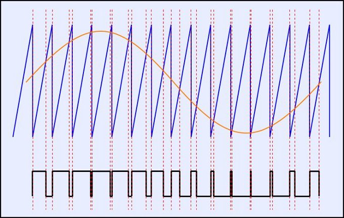
I am a newbie to verilog and just got a hold of a FPGA Spartan 3E board but now im in need of some help. Of course I have done a lot of searching and reading first. Anyways, the task I am faced with is to use a Look-up table to generate PWM that will be outputted into an RC filter which will convert my PWM to a 60 Hz sinewave. My board runs at 50 MHz. I am not sure how to use the look up table to create the PWM that will eventually become a 60 Hz sine wave.
ANY feedback is greatly appreciated!

Thanks,
Joe
 

The basic principal is that, after filtering, a narrow pulsewidth will yield a low voltage and a wide pulse width will yield a high voltage. Your lookup table will be a table of pulse-widths that correspond to the levels of your sinewave. For example, lets say you use a 36 element table. Each element would represent a ten-degree step through the sine wave. Element 0 would correspond to sine(0), element 1 would be sine(10), element 2 would be sine(20), and so on.
 
The basic principal is that, after filtering, a narrow pulsewidth will yield a low voltage and a wide pulse width will yield a high voltage. Your lookup table will be a table of pulse-widths that correspond to the levels of your sinewave. For example, lets say you use a 36 element table. Each element would represent a ten-degree step through the sine wave. Element 0 would correspond to sine(0), element 1 would be sine(10), element 2 would be sine(20), and so on.

Hello barry,
Thanks for your response, your answer is very helpful. I guess my only issue at this point after make the table is not knowing how to include it in my code. I did a little more reading and saw that the simplest way would be to use a "case" module?
Either way thanks again you rock man!


mnfsoft, the second link you provides comes in very handy and is a visual representation of what barry was trying to tell. I have a pretty good idea of what my output from the board needs to look like but im still not fully sure on how to code it to get this:


For a 36-element table between 0-360 degrees I calculated these numbers:
0, 43, 86, 125, 161, 192, 217, 235, 246, 250, 246, 235, 217, 192, 161, 125, 86, 43, 0, -43, -86, -125, -161, -192, -217, -235, -246, -250, -246, -235, -217, -192, -161, -125, -86, -43

How can I put these into xilinx verilog code using the "case" compare way?
Knowing that my clock default input is 50 MHz what should I do with my clock divider?

Thanks for the input!
 

I don't speak Verilog, but I'd first offset your table by 255 so that all the numbers are positive (you can't have a negative pulse width). Then you're going to have to generate a 60x36=2160Hz clock (60 Hz output, 36 samples per cycle). This clock would increment a counter that generates the index into your table. Voila!
 
Status
Not open for further replies.

Part and Inventory Search

Welcome to EDABoard.com

Sponsor

Back
Top