Continue to Site

Welcome to EDAboard.com

Welcome to our site! EDAboard.com is an international Electronics Discussion Forum focused on EDA software, circuits, schematics, books, theory, papers, asic, pld, 8051, DSP, Network, RF, Analog Design, PCB, Service Manuals... and a whole lot more! To participate you need to register. Registration is free. Click here to register now.

[moved] Noob question on projection alarm clock

Status
Not open for further replies.

Dusty Vander Plaats

Newbie level 1
Joined
May 31, 2015
Messages
1
Helped
0
Reputation
0
Reaction score
0
Trophy points
1
Activity points
12
Hey all- I would really appreciate some help with this, as, apparently, I have no idea what I'm doing.

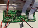
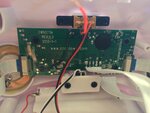
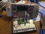
Attached are three images of the innards of my new projection alarm clock that gives the time and temp on the ceiling or wall. I did not know that the projection would have to be activated by vibration and then would only stay on for 8 seconds. I was hoping that the projection would remain active at all times, projecting the necessary information on the wall constantly. I thought it would be rather straight forward to find the switch that is vibration sensitive and bypass it so the projection would stay on at all times, but even when I do, there is a timer that is still working on the circuit that, again, shuts the projection off after 8 seconds. I don't know if anyone can help me, but I thought I would try.

Thanks in advance,

Dusty
 

Attachments

  • IMG_2961.JPG
    IMG_2961.JPG
    2.2 MB · Views: 75
  • IMG_2962.JPG
    IMG_2962.JPG
    1.5 MB · Views: 73
  • IMG_2963.JPG
    IMG_2963.JPG
    1.8 MB · Views: 64

I agree with Barry but I add that I can't see what part is detecting the vibrations. There is what might be a microphone in the third picture to the right of the circuit board, mounted on the plastic case but without seeing the front side it could be anything.

This *might* work but without the technical info on the product it is impossible to be sure:

Get hold of a silicon diode, type 1N400x where 'x' is 1 through 7, they cost almost nothing. Modules like that one tend to be 'universal' with functions built in which your particular clock doesn't use. It may be that the option for timer or continuous display is one of the options. To customize it for particular products, the module manufacturer uses either solder links or sometimes diodes which can be fitted or omitted at final assembly stage. Looking at the first photograph, on the left side there is a line of 10 solder pads marked D7 through D11, there are likely candidates for customization options. Bend the legs of the new diode so they are parallel and about the same spacing as the pads and hold it so the legs bridge the other pad pairs like D7 and D10 do at the moment. In one position it may override the timer. It may also be possible that removing D7, D10 or both disables it, you will have to experiment with different combinations to find out. The band on the new diode body should match the band on the existing diodes, in other words toward the pad at the edge of the board. Their presence is read by the chip under the black epoxy blob so exactly what they do is decided by the software and hardware of that component and I doubt you could even trace it's manufacturer, even if you did they would not divulge data to you unless you placed an order with them for quantities in the thousands!

Brian.
 

Status
Not open for further replies.

Part and Inventory Search

Welcome to EDABoard.com

Sponsor

Back
Top