Continue to Site

Welcome to EDAboard.com

Welcome to our site! EDAboard.com is an international Electronics Discussion Forum focused on EDA software, circuits, schematics, books, theory, papers, asic, pld, 8051, DSP, Network, RF, Analog Design, PCB, Service Manuals... and a whole lot more! To participate you need to register. Registration is free. Click here to register now.

[Moved] Interfacing gsm sim 900 to mcb2140

Status
Not open for further replies.

sheetal d

Newbie level 4
Joined
Jul 1, 2014
Messages
5
Helped
0
Reputation
0
Reaction score
0
Trophy points
1
Activity points
46
can i connect p0.0 and p0.1 of mcb2140 to modem's Rx and Tx or should i use serial ports com 0 and com1 of mcb2140 and give its output to max232.
gsm modem is of simcom and i find that it has an in built max232
 

The GSM modem having max232 converter,
Connect Tx(P0.0) pin of MCB2140 to Rxd pin of GSM and
Connect Rx(P0.1) pin of MCB2140 to Txd pin of GSM.
Use the these commands for sending msg
UART_transmit("AT");
UART_transmit("AT+CMGF=1");
UART_transmit("MOBILEnum");
data to sent
UART_transmit(0x1A); //for termination


can i connect p0.0 and p0.1 of mcb2140 to modem's Rx and Tx or should i use serial ports com 0 and com1 of mcb2140 and give its output to max232.
gsm modem is of simcom and i find that it has an in built max232
 

MCB2140 has dusl RS232 porst. If your SIM900 modem has RS232 port then directly interface both using a RS232 cable to the DB9 connectors. If SIM900 has TTL 5V or 3.3V type which match with TTL pins of Dev board then you can interface using TTL pins but you need to have access to Rx and Tx TTL pins of MCU on the Dev board.

I saw the board. It has header out for P0 and P1. They are TTL pins and it seems that they are 3.3V type. So, you can't connect SIM900 RS232 pins to them directly. Also are you sure P0.0 and P0.1 are UART lines of the MCU on Dev board ? I haven't checked the schematics in detail. If they are not UART pins then it is of no use if you connect 3.3V TTL pins of SIM900 if any to P0.0 and P0.1.

Edit:

I checked the schematics and indeed it is a 3.3V TTL device which is on dev board and also P0.0 and P0.1 are UART pins and they are connected to DB9 connectors through MAX232. You can interface SIM900's RS232 DB9 connector to dev boards RS232 P2 DB9 connector.


Provide link for SIM900 modem board which you have. Just to check if it has TTL or RS232 ports.
 
Last edited:
Sir the link is **broken link removed**
 

sir my project is overheating alert in remote areas using gsm. i have wriiten the code for it. but dont know where is the error. i am posting the code please help us


Code C - [expand]
1
2
3
4
5
6
7
8
9
10
11
12
13
14
15
16
17
18
19
20
21
22
23
24
25
26
27
28
29
30
31
32
33
34
35
36
37
38
39
40
41
42
43
44
45
46
47
48
49
50
51
52
53
54
55
56
57
58
59
60
61
62
63
64
65
66
67
68
69
70
71
72
73
74
75
76
77
78
79
80
81
82
83
84
85
86
87
88
89
90
91
92
93
94
95
96
97
98
99
100
#include <stdio.h>
#include <LPC214x.H>                    /* LPC214x definitions */
#include "lcd.h"
#include "adc.h"
void wait(int count)
{
  int j=0,i=0;
  for(j=0;j<count;j++)
  {
    /* At 60Mhz, the below loop introduces
    delay of 10 us */
    for(i=0;i<35;i++);
  }
}
int process_adc()
{
float x,y,z;
unsigned short adc_value = 0;
unsigned char buf[16] = {0};
PINSEL0 = 0x00050005;
U1LCR = 0x83;               /* 8 bits, no Parity, 1 Stop bit   */
U1DLL = 97;                /* 9600 Baud Rate @ 15MHz VPB Clock */
U1LCR = 0x03;
adc_value= adc_read(ADC0, CHANNEL_3); 
x= adc_value;
y=x*5.0*100/1024;
z=(y*100)/100;
sprintf((char *)buf, "ADC:%d ", z);
lcd_putstring(LINE1, (char *)buf);
return x; 
}
int main (void) 
{
float x;
static char *string;
init_adc0(); // Initialize ADC
init_lcd(); // Initialize LCD
wait(100000);
lcd_clear(); // clear display
while(1)
{
x=process_adc();//Raed ADC value and display it on first line of LCD
wait(30);
if(x>300)
{
string="AT+CMGS=";
while(*string != '\0')
{
while(!(U1LSR & 0x20));
U1THR=*string;
string++; 
delay(3);
}
while(!(U1LSR & 0x20));
U1THR=34;
string="9986979772";
while(*string != '\0')
{
while(!(U1LSR & 0x20));
U1THR=*string;
string++; 
delay(3);
}
while(!(U1LSR & 0x20));
U1THR=34;
while(!(U1LSR & 0x20));
U1THR=13;
string="PLANT OVERHEATING";
while(*string != '\0')
{
while(!(U1LSR & 0x20));
U1THR=*string;
string++; 
delay(3);
} 
while(!(U1LSR & 0x20));
U1THR=13;
string="PLEASE DO CHECK";
while(*string != '\0')
{
while(!(U1LSR & 0x20));
U1THR=*string;
string++; 
delay(3);
} 
while(!(U1LSR & 0x20));
U1THR=13;
while(!(U1LSR & 0x20));
U1THR=26;
delay(70000);
lcd_clear() ;
IODIR1=0XFFFFFFFF;
while(1)
{
lcd_putstring(0,"OVERHEATING");
IO1SET=0X3000000;
delay(70000);
IO1CLR=0X3000000;
delay(70000);
}}}}

 
Last edited by a moderator:

Hi Sheetal

I have never used LPC MCUs. I have modified your code. Please check if it works. I can't tell anything about your core UART code.

You need a 12V 2A adapter because SIM900 draws 1 to 1.5A while sending SMS. Connect SIM900A to dev board using RS232 DB9 connectors. Use a serial cable.


Code C - [expand]
1
2
3
4
5
6
7
8
9
10
11
12
13
14
15
16
17
18
19
20
21
22
23
24
25
26
27
28
29
30
31
32
33
34
35
36
37
38
39
40
41
42
43
44
45
46
47
48
49
50
51
52
53
54
55
56
57
58
59
60
61
62
63
64
65
66
67
68
69
70
71
72
73
74
75
76
77
78
79
80
81
82
83
84
85
86
#include <stdio.h>
#include <LPC214x.H> /* LPC214x definitions */
#include "lcd.h"
#include "adc.h"
 
void wait(int count)
{
    int j=0,i=0;
    for(j=0;j<count;j++)
    {
        /* At 60Mhz, the below loop introduces
        delay of 10 us */
        for(i = 0; i < 35; i++);
    }
}
 
double process_adc()
{
    double adc_value = 0;
    unsigned int char[16] = {0};
    PINSEL0 = 0x00050005;
    U1LCR = 0x83; /* 8 bits, no Parity, 1 Stop bit */
    U1DLL = 97; /* 9600 Baud Rate @ 15MHz VPB Clock */
    U1LCR = 0x03;
    adc_value = adc_read(ADC0, CHANNEL_3) * 500.0 / 1023.0; 
    sprintf((char *)buf, "ADC:%d ", adc_value);
    lcd_putstring(LINE1, (char *)buf);
    return adc_value; 
}
 
void UART_Write(char uartData) {
    
    while(!(U1LSR & 0x20));
    U1THR = uartData;       
    delay(3);
    
    while(!(U1LSR & 0x20));
}
 
void UART_Write_String(char *str) {
    while(*str)
    {
        UART_Write(*str++);
    }
    while(!(U1LSR & 0x20));
}
 
int main (void) 
{
    double x = 0.0;
    char *string = "                        ";
    init_adc0(); // Initialize ADC
    init_lcd(); // Initialize LCD
    wait(100000);
    lcd_clear(); // clear display
    
    while(1)
    {
        x = process_adc();//Raed ADC value and display it on first line of LCD
        wait(30);
 
        if(x > 300.0)
        {
            str="AT+CMGS=";
            UART_Write_String("AT\r");
            //2 sec delay here
            UART_Write_String("AT+CMGF=1\r");
            //2 sec delay here
            UART_Write_String("AT+CMGS=\"9986979772\"\r");
            //2 sec delay here
            UART_Write_String("PLANT OVERHEATING\r\n");
            UART_Write_String("PLEASE DO CHECK\r");
            UART_Write(0x1A);
            
            delay(70000);
            lcd_clear() ;
            IODIR1=0xFFFFFFFF;
            
            lcd_putstring(0,"OVERHEATING");
            IO1SET=0x3000000;
            delay(70000);
            IO1CLR = 0x3000000;
            delay(70000);           
        }
    }
}

 
Last edited:

Interfacing gsm to mcb2140

Sir i tried the code given by u but still i was not able to get the output.i checked the modem through hyperterminal and was able to send messages successfully. Can u help us to figure the problem
 

Re: Interfacing gsm to mcb2140

What sensor are you using ? PT100 ? Change if(x > 300.0) to if (x) and see. Maybe you are getting x < 300. If you are using LM35 then your calculation is wrong.

If LM35 is used you get 1.5V for 150 degree C. If your MCU works at 3.3V then you get 1023 for 3.3V adc input.

In code you are using UART1 and not UART0. So, use COM1 DB9 Connector to connect to SIM900's DB9 connector.


Code C - [expand]
1
2
3
4
5
6
7
8
9
10
11
12
13
14
15
16
17
18
19
20
21
22
23
24
25
26
27
28
29
30
31
32
33
34
35
36
37
38
39
40
41
42
43
44
45
46
47
48
49
50
51
52
53
54
55
56
57
58
59
60
61
62
63
64
65
66
67
68
69
70
71
72
73
74
75
76
77
78
79
80
81
82
83
84
85
86
87
88
89
90
91
92
93
#include <stdio.h>
#include <LPC214x.H> /* LPC214x definitions */
#include "lcd.h"
#include "adc.h"
 
void init_serial (void);
int putchar (int ch);
 
void wait(int count)
{
    int j=0,i=0;
    for(j=0;j<count;j++)
    {
        /* At 60Mhz, the below loop introduces
        delay of 10 us */
        for(i = 0; i < 35; i++);
    }
}
 
void init_serial (void)                   /* Initialize Serial Interface       */
{
  
  PINSEL0  = 0x00050005;         
  U1LCR = 0x00000083;         /* 8 bits, no Parity, 1 Stop bit     */
  U1DLL = 97;         /* 9600 Baud Rate @ 15MHz VPB Clock  */
  U1LCR = 0x00000003;        /* DLAB = 0                          */
}


double process_adc()
{
    double adc_value = 0;
    unsigned int char[16] = {0};
    
    adc_value = adc_read(ADC0, CHANNEL_3) * 500.0 / 1023.0; 
    sprintf((char *)buf, "ADC:%d ", adc_value);
    lcd_putstring(LINE1, (char *)buf);
    return adc_value; 
}
 
void UART_Write(char uartData) {
    
    while(!(U1LSR & 0x20));
    U1THR = uartData;    
}
 
void UART_Write_String(char *str) {
    while(*str)
    {
        UART_Write(*str++);
    }    
}
 
int main (void) 
{
    double x = 0.0;
    char *string = "                        ";
    init_adc0(); // Initialize ADC
    init_lcd(); // Initialize LCD
    wait(100000);
    lcd_clear(); // clear display
    init_serial();
  
    while(1)
    {
        x = process_adc();//Raed ADC value and display it on first line of LCD
        wait(30);
 
        if(x)
        {
            UART_Write_String("AT\r");
            delay(30000);
            UART_Write_String("AT+CMGF=1\r");
            delay(30000);
            UART_Write_String("AT+CMGS=\"9986979772\"\r");
            delay(30000);
            UART_Write_String("PLANT OVERHEATING\r\n");
            UART_Write_String("PLEASE DO CHECK\r");
            UART_Write(0x1A);
            
            delay(70000);
            lcd_clear() ;
            IODIR1=0xFFFFFFFF;
            
            lcd_putstring(0,"OVERHEATING");
            IO1SET=0x3000000;
            delay(70000);
            IO1CLR = 0x3000000;
            delay(70000);           
        }
    }
}

 
Last edited:

Re: Interfacing gsm to mcb2140

SIR I TRIED THE GIVEN CODE AND CONNECTED COM1 TO DB9 OF GSM MODEM. I AM USING ADAPTER OF 12V 700mA.BUT STILL NO OUTPUT..
 

Re: Interfacing gsm to mcb2140

I already mentioned that SIM900 needs 1.5A current to send SMS. Remove if(x) and try.
 

You can can power a SIM900 from a 500mA source for example a USB port.

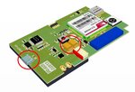
I manufacture a range of Personal / Asset Tracker devices than can be powered from a USB port.

In our design there are 2 x 470uF Low ESR Tantalum Capacitors mounted close to the SIM900 supply pins.

See included CAD drawing example.

Cheers.

MTX-PT.jpg
 

Status
Not open for further replies.

Similar threads

Part and Inventory Search

Welcome to EDABoard.com

Sponsor

Back
Top