Continue to Site

Welcome to EDAboard.com

Welcome to our site! EDAboard.com is an international Electronics Discussion Forum focused on EDA software, circuits, schematics, books, theory, papers, asic, pld, 8051, DSP, Network, RF, Analog Design, PCB, Service Manuals... and a whole lot more! To participate you need to register. Registration is free. Click here to register now.

[Moved] Inductor design for an output inverter

Status
Not open for further replies.

Markobar

Newbie level 3
Joined
Jun 14, 2015
Messages
3
Helped
0
Reputation
0
Reaction score
0
Trophy points
1
Activity points
34
Hi everybody!

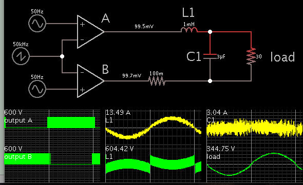
I have to design an inductor for the output filter (LC) of a 50Hz inverter (full bridge, vbus = 600V). The switching frequency is 50kHz and the output voltage is 230Vac. The RMS value of the current through the inductor is 8A.

Now the complicated part:
The current through the inductor has a low frequency component of 50Hz and a high frequency ripple of 50kHz. The ripple amplitude is mainly a function of the inductor value. The output capacitor value also changes the ripple amplitude, but much less than the inductor value (we can suppose C = 2.2uF or 4.4uF).

After some simulations, I get (the RMS value of the current is 8A):

For an inductor value of 200uH, the 50kHz ripple (pk-pk) is 14A
For an inductor value of 400uH, the 50kHz ripple (pk-pk) is 6.5A
For an inductor value of 600uH, the 50kHz ripple (pk-pk) is 4.5A
For an inductor value of 1mH, the 50kHz ripple (pk-pk) is 3A

What would be the best choice for the inductor value? (any value between 200 and 1000uH is possible)
And once the value has been determined, is there a commercial inductor (or two to be connected in parallel or series) fulfilling all the specifications or how would you do to build it (core material and shape, litz wire or not, turns, etc.)? The idea is to find a trade off between losses and size.

Thank you in advance!
 

In a basic sense you are constructing an LC second order butterworth filter.

Select the inductor to start its rolloff curve around 80-100 Hz.

Select the capacitor so that it corrects for power factor. The Ampere waveform must align with the voltage waveform.

As a rough formula, the capacitor and load should have about the same impedance as the load at 50 Hz.
Notice that the capacitor powers the load for a portion of the cycle, therefore the same amount of going through them at that time.

You can vary the L & C values as necessary, in order to shape the waveform going to the load.
 
Thank you for your reply BradtheRad.

The power factor is not a problem for my design. All the values of L in the 200-1000uH interval should work fine. More than the inductor value, my problem is how to build it as a physical component (core, number of turns, etc.) taking into account size, saturation and losses.

I am sure that it is possible to build a 200uH inductor with a saturation current of 18.3A (8 Arms and a 50kHz ripple of 14A) and a 1mF inductor with a saturation current of 12.8A (8 Arms and a 50kHz ripple of 3A). But they must be very different in size and losses (it is not the same a 50kHz 14A ripple than only 3A). I think there must be an optimum between these both extreme cases.

Thank you again!
 

This is quite a tough problem to solve, as there are many aspects to consider.

I recently had the opportunity out of curiosity to reverse engineer a very similar filter choke that came out of a commercial 1.5 Kw 240 volt grid tie inverter that switched at 20 Khz.

This particular circuit is a full bridge operating at 200 volts dc and drove the primary of a 2:1 toroidal step up transformer to transform 120 primary volts to 240 secondary volts. Its a bit different to what you are doing, but nevertheless its still kind of relevant in a way...

The series choke is 2.7mH, and rated at 15 amps rms, the shunt capacitor being 5uF. By measurement, the shunt capacitor resonated with the transformer primary inductance at about 85 Hz. It seems that this avoided any large resonant buildup of energy at 50 Hz when the inverter runs unloaded. And the 5uF was sufficient to shunt most of the 20 Khz switching energy.

Now the choke itself is a pair of very ordinary cut C cores made from wound 0.3mm grain oriented silicon steel strip. Cross sectional area 16mm x 40mm.
There are two windings each of 44 turns of 2.8mm wire, one on each limb, connected in series. It is not known if there is an air gap hidden in there, but its quite possible.

This choke mostly has to withstand about 13 amps of 50 Hz current, and the grain oriented core will have a suitably high flux saturation level to handle that.

But at 20 Khz, the flux swing will be 400 times less, and the resulting eddy current heating loss in the core appear to be so low that it is not a concern !

I did work all the magnetics out, but that particular piece of paper is now long gone.
As for the origin of this choke, it was a Chinese manufactured product, and I could find nothing on the internet about either the Company that made it, or the particular choke.

I rather gather it was probably custom wound for the inverter manufacturer, and probably not an item for general sale as a standard component, so no luck there.
 
Last edited:
Thank you very much for your answer, Warpspeed.

It is a difficult problem. If I find a solution, I will post it here.
 

I am sure that it is possible to build a 200uH inductor with a saturation current of 18.3A (8 Arms and a 50kHz ripple of 14A) and a 1mF inductor with a saturation current of 12.8A (8 Arms and a 50kHz ripple of 3A).

Since it only needs to carry 11A peak, I suspect it's okay if the flux field does not build further beyond that. There is no need for it to respond to spikes which extend beyond that amplitude.
 

I think I figured out what your design is like. Here is my very simple simulation.

Inductor 1 mH. Capacitor 3 uF (in your suggested range).

For a while I was going to insist the inductor should be 30mH or more, in order to provide an inductive drop from 600 V to 330 VAC (peak) at 50 Hz. Finally I realized you will shorten all PWM pulses to achieve this.


Power factor appears okay, as you expect.

Notice that the capacitor will have several Amperes going back and forth through it, at high speed. This could burden a small value cap. Therefore it might be a good idea to parallel a gang of them.

It's up to you which is more practical, a gang of caps, or adding more turns on your inductor.
 

Status
Not open for further replies.

Part and Inventory Search

Welcome to EDABoard.com

Sponsor

Back
Top