joshff91
Newbie level 2

- Joined
- Feb 14, 2015
- Messages
- 2
- Helped
- 0
- Reputation
- 0
- Reaction score
- 0
- Trophy points
- 1
- Activity points
- 20
Hi
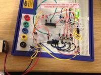
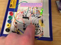
I cant get the Data LED's, at the decoder, to respond to my input from the encoder, any ideas? thanks. Pictures underneath...
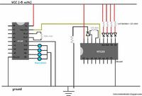
I have recently purchased a few HT12E and HT12D ICs. i made a remote circuit using - letslearnelectronics.blogspot.in/2012/07/introduction-to-encoding-and-decoding_1610.html?view=sidebar
I have also been using holtek data sheets
HT12E - holtek.com/pdf/consumer/2_12ev120.pdf
HT12D - holtek.com/pdf/consumer/2_12dv120.pdf
I can get the valid transmission (VT) LED to energise and de-energise using a switch @ the TE pin on the encoder side of the circuit, or i can get it to permanently energise by connecting the TE pin to ground (active low) - this works as expected from reading both data sheets. However i cannot get the four LED's which are connected to the decoders data line to respond to the input from the encoder. They are permanently on. I have looked at many versions of this circuit online and they all seem to be the same. They all reccomend using switches on the data input @ the encoder.
Like i said all 4 of my leds stay energised....
Any help would be great thanks


