Continue to Site

Welcome to EDAboard.com

Welcome to our site! EDAboard.com is an international Electronics Discussion Forum focused on EDA software, circuits, schematics, books, theory, papers, asic, pld, 8051, DSP, Network, RF, Analog Design, PCB, Service Manuals... and a whole lot more! To participate you need to register. Registration is free. Click here to register now.

[MOVED] How to find Vt of a MOS transistor (NMOS or PMOS)

Status
Not open for further replies.

seamoss

Junior Member level 3
Joined
Jun 14, 2012
Messages
26
Helped
0
Reputation
0
Reaction score
0
Trophy points
1,281
Activity points
1,453
I was looking at simple way to find Vt of a NMOS transistor, I figured, I could apply vdd on the gate and vdd on the drain and see the source dc level. So whatever the source dc level minus vdd is the Vt of the cell. Am I doing something wrong here ?

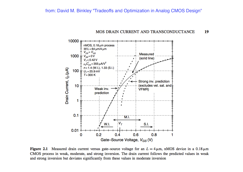
Just to cross check, I did a DC simulation applying vdd/2 on drain, sweeping Vgate and plotting the current, now I see a different Vt at which the transistor starts to conduct. Why do I See two different Vts for two different types of simulation ?
 

Re: How to find Vt of a MOS transistor (NMOS or PMOS)

Is this on a custom IC process or discrete device? Where are you connecting the bulk to?

Keith
 

Re: How to find Vt of a MOS transistor (NMOS or PMOS)

Is this on a custom IC process or discrete device? Where are you connecting the bulk to?

Keith

This is not a discrete device. This is a pure simulation using a CMOS process.
 

Re: How to find Vt of a MOS transistor (NMOS or PMOS)

So where have you connected the bulk?

Keith

- - - Updated - - -

Note: thread moved to correct section
 

Re: How to find Vt of a MOS transistor (NMOS or PMOS)

So where have you connected the bulk?

Keith

- - - Updated - - -

Note: thread moved to correct section

Sorry, in both cases I have connected it to ground.
 

Apply 0.1V on the drain, ground the source and body. Sweep the gate from 0 to 1V in very small steps measuring the drain current.
From the graph of Vgs vs Ids, find the maximum slope (dIds/dVgs) and draw a line to Ids = 0 (intercept with Vgs axis).
From this intercept value subtract 0.05V (0.5*Vds) and this is the threshold voltage.
 

I think this definition results in a Vgs which belongs to the deep weak inversion region, aka subthreshold, see e.g. this Id vs. Vgs curve:

Usually the threshold voltage (VT in the above image) is defined via a process-dependent technology current and the W/L ratio of the MOSFET.
 

What (I tried) to desribe - very simplistically, is the actual way in which a Fab measures the Vt of each MOS transistor at paramteric probe prior to functional probe. This is the Linear Threshold Voltage obtained at max Gm and is pretty much industry standard. The W/L ratio is used to determine the Leff and Weff once the Vt and Ids values are obtains for narrow and wide variations of L and W. Subthreshold is measured by finding the sub threshold slope of Vgs vs Ids.
Of course this is for Fab measurements and does not apply beyond discrete components on an IC.
 

The fabs I've been in, have usually taken several VTs - at
least VTlin and VTsat, sometimes a scaled current density
VT (like 1uA on a 1-square device).

Doing a source-follower Vgs measurement with an appropriate
Vds, and Vbs=0, and a source current forced, is a not-useless
way to go, although it may not match any of the standard
methods especially well.

What you want out of it, would indicate how fancy a method
you want to use. Something like, say, embedding the device
in a simulation testbench so you can monitor VTN and VTP
across iterations and make sense of results / sensitivity,
probably just wants simple direct OP() from a simple bias
and call it good enough.
 

Status
Not open for further replies.

Part and Inventory Search

Welcome to EDABoard.com

Sponsor

Back
Top