Continue to Site

Welcome to EDAboard.com

Welcome to our site! EDAboard.com is an international Electronics Discussion Forum focused on EDA software, circuits, schematics, books, theory, papers, asic, pld, 8051, DSP, Network, RF, Analog Design, PCB, Service Manuals... and a whole lot more! To participate you need to register. Registration is free. Click here to register now.

[moved] Frequency Synthesizer using CD4046 PLL / Frequency Multiplication

Status
Not open for further replies.

wfg42438

Member level 3
Joined
Jun 29, 2015
Messages
54
Helped
0
Reputation
0
Reaction score
0
Trophy points
6
Location
California
Activity points
620
Hello, I am trying to design a frequency synthesizer with the use of the CD4046B IC which is a PLL. Based on some research I have done I see that this is possible with the addition of a divide by N counter in the feedback loop between the VCO and phase comparator input. Before doing this there are resistors and capacitors that have to be designed for, they depend on the frequency ranges you decide to work with.

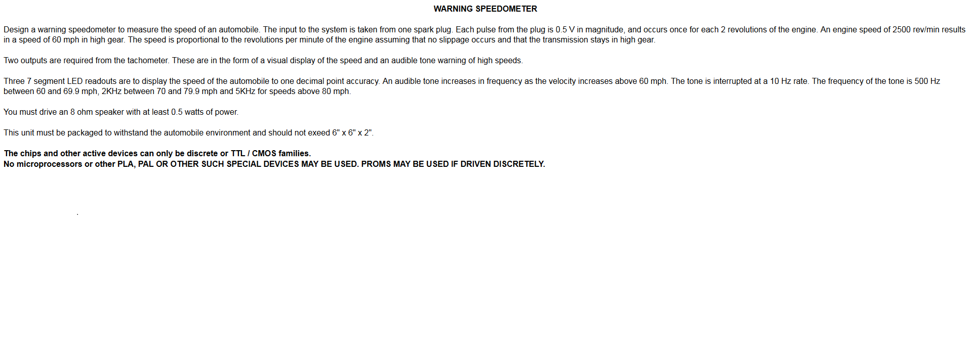
This design will be used as a subsystem in a project but in order to keep things simple let me list the relevant specs to PLL only. This circuit will simulate a speedometer, based on the frequency of the input signal we wish to convert this to MPH reading.

The specification given to start off with is:
1) The input is a pulse of 0.5V magnitude occurring every two revolutions
2) 2500 Rev/ Min = 60MPH -------- 1250 Pulses/min = 60 MPH

Based on this information I see the following:
X * 1250 Pulses/min = 60 MPH therefore ------ X = 2.88 MPH/Freq_Pulse

Now let’s assume the input has been ran through a Schmitt trigger which has cleaned up the signal (giving it logic levels of 0V (Low) and 5V (High State)) with the same frequency as our original input.

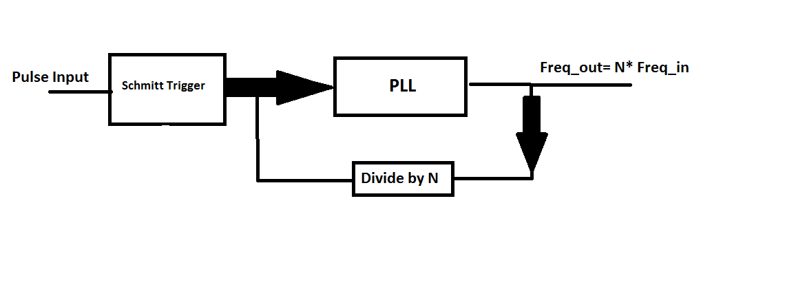
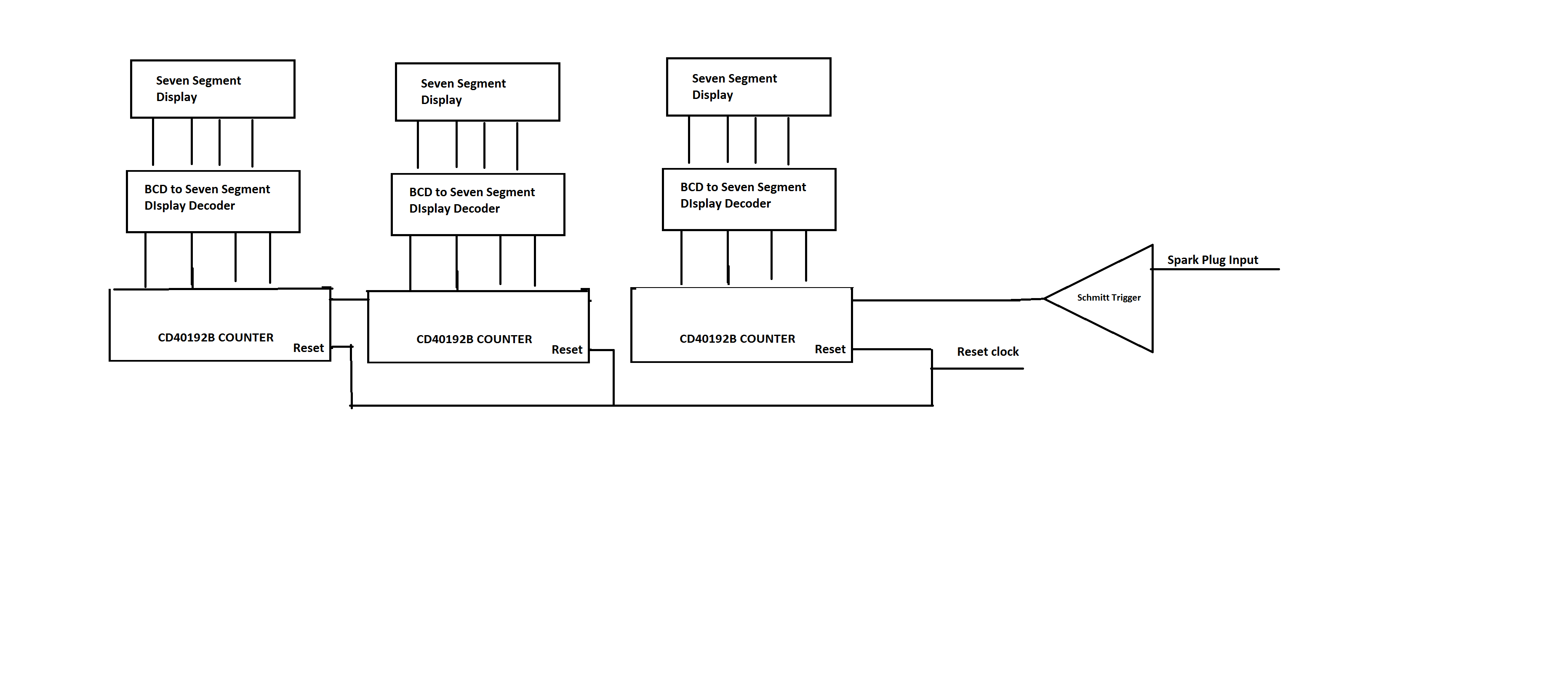
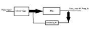
So the idea here is to take the signal at the output of the Schmitt trigger and input that into our PLL. Now if the PLL is designed appropriately we can convert the incoming frequency to MPH by multiplying the input frequency by a value N (Please see attached block diagram). Now I’m assuming multiplying by 2.88 will not be easy therefore I think the next best thing we will need to multiply by 288. I’m assuming once I move on to the counter it can be manipulated one more time to get us the correct N multiplier however lets hold off on that and focus on the PLL design for now.

Based on the data sheet I have found the following:
If VDD=5V, N=288

For the VCO let’s see what the lowest and highest frequencies we will produce:
Let the lowest speed we can display be 10 MPH & the highest be 99.9 MPH

Therefore: fmin= (10 MPH)/( 2.88) )* 288 = 999.99 Hz --- let fmin=1kHz

Fmax= (99.9 MPH)/ (2.88))* 288= 9.999 kHz - let Fmax=10kHz


Using the data sheet limits and graphs we arrive at:
Fmax/fsmin = 10 , f_center= 5.5 kHz & R2/R1 = 20

Next letting R1= 10k R2 =200k, C1=6800pF

For the Filter it was found: R4=2.7k, C2=3.9 uF, , & R3=6.2k


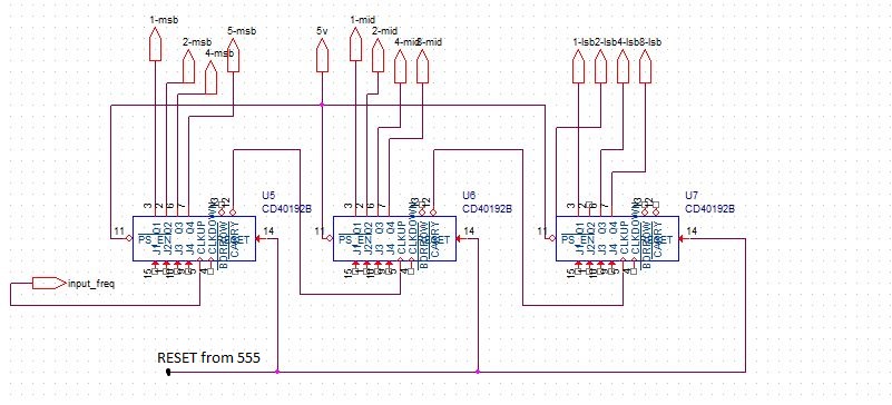
Now under the assumption that the external Caps and resistors R1-R4 & C1-C2 are chosen correctly how do I go about introducing the divide by N block into the feedback loop?


https://www.mouser.com/ds/2/405/cd4046b-439718.pdf

- - - Updated - - -

Adding the Block Diagram:


Re: Frequency Synthesizer using CD4046 PLL / Frequency Multiplication

1250 Pulses/min = 60 MPH

This works out to 21 pulses per second.

How often do you wish to update your display? Is 3.47x per second reasonable? Seems to me your job is easier if you were to do it that way. Take the count every 0.288 second. That automatically gives you the mph (although it's divided by 10, and an integer). You'll need to do some fancy arithmetic to have a more precise reading.
 

After I did some thinking, perhaps I get it now. Your plan is to multiply a few counts per second, by a scaler so that you also have some fractional part in between the integer values. Which is to say, since you want readings between 50 and 60 mph, you need to generate additional pulses at a faster and proportional and linear rate. The PLL is an analog method to do this.

An alternate method is to count clock cycles between each event. Or combine methods, to obtain number of events, plus a certain number of clock cycles after the latest event. To get mph, the arithmetic probably involves division, which may be difficult in analog circuitry.
 

Look at the problem from the other side. 1250 pulses/min is a rather small number ---> about 21 pulses /sec. In such counting, you often miss one (in the beginning or near the end) or end up with one excess (count both the start and end pulses). So there will always be an uncertainly of +/- 1. In this context, the error will be +/- 5%. If you want to update the display every 1/2 sec, the error will increase to 10%. Perhaps 5% error rate will be acceptable but there will be demand to have better accuracy.

Better to have the count for 2 second and update the screen every 2 second. That is the best that can be done with the present setup you have proposed.
 

Re: Frequency Synthesizer using CD4046 PLL / Frequency Multiplication

This works out to 21 pulses per second.

How often do you wish to update your display? Is 3.47x per second reasonable? Seems to me your job is easier if you were to do it that way. Take the count every 0.288 second. That automatically gives you the mph (although it's divided by 10, and an integer). You'll need to do some fancy arithmetic to have a more precise reading.


Due to time constraints id like to explore a simpler design as you are proposing can you elaborate more?

Would this simply be a set of cascaded counters being reset every 0.288 seconds which means a 3.47 Hz clock would be used ? Can a clock signal this low in frequency be generated?

I have attached a block diagram i made based on what i think you are proposing please let me know if this is the case

Please note im considering using CD40192BE counters and CD4511BE decoders

The additional image displays the set up of the counters considered


If a microcontroller is completely out of the question, then it becomes much more difficult to get really good results.

At low road speeds, the pulse frequency will be so low that the PLL is going to need a very long time constant, and readings will either be painfully slow to change, or there will be annoying jittery fluctuations in the readout.

Another totally different approach to all this might be to convert the incoming pulses to a dc voltage, then use a digital voltmeter to display the speed.
Say 6.00 volts = 60.0 Mph.
20.8Hz = 6.00v

One way to convert frequency to a voltage is to use a frequency to voltage converter chip (tachometer chip) running at ultra low frequency. That is probably the simplest approach that I can see having a chance of working reasonably well.
 
Last edited:

If a microcontroller is completely out of the question, then it becomes much more difficult to get really good results.

At low road speeds, the pulse frequency will be so low that the PLL is going to need a very long time constant, and readings will either be painfully slow to change, or there will be annoying jittery fluctuations in the readout.

Another totally different approach to all this might be to convert the incoming pulses to a dc voltage, then use a digital voltmeter to display the speed.
Say 6.00 volts = 60.0 Mph.
20.8Hz = 6.00v

One way to convert frequency to a voltage is to use a frequency to voltage converter chip (tachometer chip) running at ultra low frequency. That is probably the simplest approach that I can see having a chance of working reasonably well.


Hello Tony,

Unfortunately the specifications state microprocessors cant be used and the MPH reading needs to be displayed on seven segment displays
 

Hello Tony,

Unfortunately the specifications state microprocessors cant be used and the MPH reading needs to be displayed on seven segment displays

I actually have dreams about some of the projects you guys have.
Anyhow, woke up with another idea, purely digital, no microprocessor, and seven segment readout. Fast update, and VERY accurate...

Brad has the right idea in post #3

Start out with a fast accurate clock that runs at exactly 512 Hz. This can be obtained from a 32,768 Hz watch crystal divided down by 64

Feed this into a twelve stage ripple counter that is reset to zero on the arrival of each of your incoming pulses. In other words time interval measurement between the arriving pulses.

At 60 Mph we have 1250 pulses per minute or 20.83 Hz
The ripple counter will count up to 512/20.83 or 24.57 counts. (it will be either 24 or 25)

At 1 MPH the pulses will be sixty times longer or at 0.347Hz. The ripple counter will count up to 512/0.347 or 1475.5 counts.
The ripple counter data even at only 1 Mph will update about every three seconds. At 60 Mph or data updates 20 times per second.

Now what we do is connect the 12 parallel outputs of our ripple counter into an EPROM. A 27C16 has twelve address lines.

We can program a lookup table in the EPROM such that the eight output bits drive two seven segment displays via an eight bit latch.

The EPROM lookup table can be programmed to give speed readout from 1 Mph to 99 Mph in 1 Mph steps.

This basic idea could be improved to force the display to 00 Mph when stationary by using ripple counter overflow.

A further embellishment could be re arranging the eight bits from the EPROM to drive three seven segment displays. The upper three bits drive the MSB which only need go up to seven. And the lower bit can drive an LSB digit that is either 0 or .5 Mph.

So we get 00.0 Mph to 79.5 Mph readout needing only eight bits from the EPROM.

All this should give a very accurate speed reading with 0.5 Mph resolution and a very fas update at any practical road speed.

Another advantage of this is that period counters always have a one count ambiguity. The last digit flickers between counts.
By using a high pulse count (25 at 60 Mph) our lookup table effectively eliminates the flicker problem, because all the values either side of 25 counts will read 60 Mph.

In fact the EPROM should be programmed to read 60 Mph anywhere between 59.5 Mph and 60.5 Mph. So the LSB digit flicker problem is gone !
 
  • Like
Reactions: CataM

    CataM

    Points: 2
    Helpful Answer Positive Rating
I actually have dreams about some of the projects you guys have.
Anyhow, woke up with another idea, purely digital, no microprocessor, and seven segment readout. Fast update, and VERY accurate...

Brad has the right idea in post #3

Start out with a fast accurate clock that runs at exactly 512 Hz. This can be obtained from a 32,768 Hz watch crystal divided down by 64

Feed this into a twelve stage ripple counter that is reset to zero on the arrival of each of your incoming pulses. In other words time interval measurement between the arriving pulses.

At 60 Mph we have 1250 pulses per minute or 20.83 Hz
The ripple counter will count up to 512/20.83 or 24.57 counts. (it will be either 24 or 25)

At 1 MPH the pulses will be sixty times longer or at 0.347Hz. The ripple counter will count up to 512/0.347 or 1475.5 counts.
The ripple counter data even at only 1 Mph will update about every three seconds. At 60 Mph or data updates 20 times per second.

Now what we do is connect the 12 parallel outputs of our ripple counter into an EPROM. A 27C16 has twelve address lines.

We can program a lookup table in the EPROM such that the eight output bits drive two seven segment displays via an eight bit latch.

The EPROM lookup table can be programmed to give speed readout from 1 Mph to 99 Mph in 1 Mph steps.

This basic idea could be improved to force the display to 00 Mph when stationary by using ripple counter overflow.

A further embellishment could be re arranging the eight bits from the EPROM to drive three seven segment displays. The upper three bits drive the MSB which only need go up to seven. And the lower bit can drive an LSB digit that is either 0 or .5 Mph.

So we get 00.0 Mph to 79.5 Mph readout needing only eight bits from the EPROM.

All this should give a very accurate speed reading with 0.5 Mph resolution and a very fas update at any practical road speed.

Another advantage of this is that period counters always have a one count ambiguity. The last digit flickers between counts.
By using a high pulse count (25 at 60 Mph) our lookup table effectively eliminates the flicker problem, because all the values either side of 25 counts will read 60 Mph.

In fact the EPROM should be programmed to read 60 Mph anywhere between 59.5 Mph and 60.5 Mph. So the LSB digit flicker problem is gone !


Hello Tony,

Thank you for your in depth description however before looking into this new idea on let me ask the following :

Out of curiosity and time constraints do you at all think what i proposed on post 5 would work??
 

Out of curiosity and time constraints do you at all think what i proposed on post 5 would work??

Well at 60 Mph we have 1250 pulses per minute.
Or 20.8 Hz

If you count up for only .288 seconds (3.47Hz), at 60 Mph, the count will be randomly either 6 or 5, and I cannot see that as being very useful.

If you count up for 2.88 seconds, the count will fluctuate between 60 or 59.

Three second update is fairly slow, and the reading will jump around randomly by 1 Mph at any speed.
To get rid of the random jumping you could slow down to a 5.76 second update, and ignore the jumping LSB, which would work, but is a painfully slow update.
But you will get 1 Mph resolution that way.

My proposed system updates much faster, 20 times per second at 60 Mph, two times per second at 6 Mph, and has much better resolution (0.5 Mph), and no random jumping. It would show a rock steady reading at any speed.

Its more complicated, with more parts, but its about the best result possible without using a microprocessor.
 

Tony's idea is good. You count the period rather than frequency - which lets you decide the resolution, then avoid the reciprocal problem by using a look-up table to get the results.

The only complication is the possibility of more than 99 being displayed (assuming hexadecimal is out of the question!) but that could be managed by adding a hard wired '1' if necessary or by using the existing two digits to produce a non-numeric character.

The easiest way to show the two digits is to decode the upper and lower halves of the EPROM output using 7447/4511 decoder/driver ICs. If you use a latch to use extract two segment patterns you have to double the entries in the table and also alternate between digit entries. That might cause aliasing problems at some speeds. Another alternative is a 16-bit EPROM or use two 8-bit ones, one per digit.

Brian.
 

It should be possible to latch the eight bits coming out of the EPROM, and drive two seven segment decoder chips to read 00 to 99 Mph very simply.

More than 99 cannot ever happen, because only the data programmed into the EPROM lookup table comes out of the EPROM.

As we only need three bits for the upper digit (it only need go up to 7) that gives us an extra spare bit left over.
That extra bit could be used to drive a third seven segment display that displays only either .0 or .5Mph

Its just a bit of extra fluff, but it would make the whole thing look a bit nicer.
 

Hi,

unfortunately I have to say that I don´t see a chance to operate it satifactory.

What you want to build is a PLL. It should lock to the incoming signal and multiply it´s frequency by a given factor.

The problem lies in the very slow update rate and the unpredictable change in frequency.
If you have a slow update rate you need a very slow analog filter to smoothe the output of the phase/frequency detector.

Imagine: Consider the input signal is constant and stable. It may take minutes for the output frequency to become stable.
Now you change input frequency (revolutions) and again it takes minutes to get a stable output.

****
The problem is, that the phase(or f) detector only sees phase(timing) errors. It doesn´t see an absolute value.
It sees that the VCO frequency is too low. Then it adjust it to be higher. but the filter should smooth the "error pulse" and generate a (near) DC voltage to feed the VCO.
The "smoothing filter" ideally should keep the DC voltage stable (within some x% of ripple) until the next pulse arrives.

...Some calculations:
(Some x% of ripple also means some x% of frequency change. So if it should be stable to 1% then for a raw estimation the filter cutoff frequency needs to be 1% of the lowest expectable input frequency)
You said 60MPH is 1250 pulses per minute, this means 10MPH is about 210 pulses per minute is about 3.5 pulses per second = 3.5Hz.

To smooth the ripple to 1% means about 0.035Hz cutoff frequency with a first order LPF. This means a tau of 4.5 seconds.
If you want to run a tau = 4.5s first order filter to adjust to 1% error it needs about 4.6 tau = 21seconds.

I assumed it to minutes. Now I calculated 21 seconds. Godd for you. But is it satisfactory?
This is araw estimation. In reality it may be better, or it may be worse.)

(BTW: Higher order filter may improve to reduce the ripple, but they intruduce more phase shift, resulting in oscillating PLL)

****
A solution without microcontroller is difficult. (with microcontroller it is easy)

The PLL solution is a "error cancelling" solution.. what i mean is: It generates a frequency, compares it with the incoming frequency and according the error it tries to find a better frequency.
***
I´d try to find some kind of (absolute) period time solution, where you measure the incoming period time (tp_in) and generate a frequency with 1/(t_in / factor).
I don´t know exactely how. Maybe with the use of integrators and some kind of sample_and_hold circuit (instead of RC LPF)..

Klaus
 

Out of curiosity and time constraints do you at all think what i proposed on post 5 would work??

Your second concept is suitable, although there are counter IC's which make the job easier. These manage several digits internally. You only need to add the 7-segment displays, and possibly a single driver IC. The driver IC might be 4543 or 4511.

Example, I have made projects with the 14553 (3-digit counter). Multiplexing is used so that each digit lights up one at a time, very rapidly.
 

I still favor the period counting method, the spark frequency (or wheel rotation speed frequency) can be very low. 'Wfg42438' has not explained the whole situation but I'm guessing from the expected range of results this is for a road vehicle. Using the spark frequency therefore reveals the rotational rate of the engine, not the speed along the ground which would depend on other factors, especially the crank shaft to wheel axle gear ratio and the tire diameter. An other problem is that measuring the engine roation speed will still give an MPH indication when the vehicle is out of gear and idling!

I would do it this way:
1. start with a suitable clock frequency, chosen to keep the range of counts within say 20% of zero and maximum counter range range.
2. latch the count value and reset the counter at each spark/sensor pulse. The latch then holds counts per pulse.
3. send the latched value to the lower EPROM address inputs, keep upper address lines for gear selector conversion if necessary.
4. decode the lower EPROM data bits to the MPH units digit and upper bits to the MPH tens digit.

That gives an indication update at least once per pulse and if greater precision is needed, just increase the clock frequency and counter size then use an EPROM with more address lines to cater for the larger number range. It also offsers other possibilities, for example using one address line to change from MPH to KPH.

The PLL method will certainly work but I see all kinds of problems with update rate and filtering over the relatively wide frequency range. Looking at my own vehicle, idling speed is about 800 RPM = 13Hz and top speed would be about 8000 RPM = 130Hz. A 10:1 lock-in range is quite big !

The tachometer and ADC will also work but be slow to respond but might be difficult to calibrate.

Brian.
 

Well at 60 Mph we have 1250 pulses per minute.
Or 20.8 Hz

If you count up for only .288 seconds (3.47Hz), at 60 Mph, the count will be randomly either 6 or 5, and I cannot see that as being very useful.

If you count up for 2.88 seconds, the count will fluctuate between 60 or 59.

Three second update is fairly slow, and the reading will jump around randomly by 1 Mph at any speed.
To get rid of the random jumping you could slow down to a 5.76 second update, and ignore the jumping LSB, which would work, but is a painfully slow update.
But you will get 1 Mph resolution that way.

My proposed system updates much faster, 20 times per second at 60 Mph, two times per second at 6 Mph, and has much better resolution (0.5 Mph), and no random jumping. It would show a rock steady reading at any speed.

Its more complicated, with more parts, but its about the best result possible without using a microprocessor.

Although i want to explore your original proposal i would like to attempt the design proposed in post 5 first since the due date for this assignment is coming up. I understand its not nearly as accurate as your proposal however it seems its something i can construct and test in a timely fashion which is why i want to focus on the simpler design first. The plan is to explore the design in post 5 first and if time allows also try your proposal as well as im quite interested in learning about the EPROM as i have never used one.


Now Going back to post 5,

As you mention an update time of .288 seconds would either produce 6 or 5 counts which simply would not be useful, thank you for pointing that out i did not realize that was the case


Next, if the set of counters proposed were to count up to 2.88 seconds that would mean i would need a clock of 347 mHz is that something i would be able to even generate?

Also for this scenario i would not be able obtain the correct resolution of 1 decimal point since we would produce 59 or 60 counts correct?


Now you also mentioned that we could use an update time of 5.76 Seconds in order to have the correct resolution however wouldn't that give us an invalid reading?

Say were at 60mph ---> then f=20.83 Hz

So Count= f*update_time= 119.98 counts when we are at 60 MPH

I have added the specifications of the assignment for reference. Please note there are other portions of the circuit which we have not discussed however i would like to concentrate on the display portion first as this is the part giving me the most trouble.

I also want to thank you and the rest of the users who are responding to the thread for all of the help, its much appreciated!


First thing, what test equipment do you have available ?

At the very least you are going to need something that generates some pulses to test with, from zero up to about 28 Hz.
An oscilloscope and frequency counter would be pretty essential things to have access to as well.

Three digit readout is specified with one decimal point accuracy (+/- 0.1 Mph) which is going to be very difficult requirement to achieve with ANY frequency measurement method without the speed update taking forever.

Only practical way to tackle this problem is by using period measurement, not frequency measurement. Its also interesting that a PROM is allowed in the rules, which solves the problem that period measurement produces a reciprocal result.
 

First thing, what test equipment do you have
available ?

At the very least you are going to need something that generates some
pulses to test with, from zero up to about 28 Hz.
An oscilloscope and frequency counter would be pretty essential things
to have access to as well.

Three digit readout is specified with one decimal point accuracy (+/-
0.1 Mph) which is going to be very difficult requirement to achieve
with ANY frequency measurement method without the speed update taking
forever.

Only practical way to tackle this problem is by using period
measurement, not frequency measurement. Its also interesting that a
PROM is allowed in the rules, which solves the problem that period
measurement produces a reciprocal result.

The following equipment is available to me :
DC voltage supply
Oscilloscope
Frequency counters (I've seen them around however not sure if there functional )
Function Generator (I can use that to simulate the pulse from the spark plug)


So if we were to continue using the inaccurate but simple design from post 5 how would you recommend to proceed?
 

Well, at 60 Mph. in order to read in tenths of an Mph resolution, we need to count up to 600 pulses (60.0 Mph)
As we are only receiving 20.83 pulses per second at 60 Mph, we need to count those pulses for 600/20.83 = 28.8 seconds.

And you will not be able to do that any other way with direct frequency measurement. To read 60.0 you need 600 counts.

A phase locked loop frequency multiplier, in order to get a stable output that is locked, will need to have a time constant of perhaps ten times that, or five minutes minimum, possibly more.
So its actually going to make things worse not better.

I see what you mean , what about the 5.76 second reset you suggested earlier?
 

Status
Not open for further replies.

Part and Inventory Search

Welcome to EDABoard.com

Sponsor

Back
Top