Welcome to our site! EDAboard.com is an international Electronics Discussion Forum focused on EDA software, circuits, schematics, books, theory, papers, asic, pld, 8051, DSP, Network, RF, Analog Design, PCB, Service Manuals... and a whole lot more! To participate you need to register. Registration is free. Click here to register now.
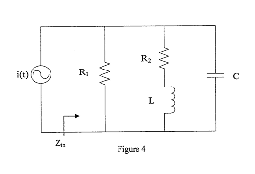
can someone help how do i find quality factor for this kind of circuit??
i know that Q=R/wL, w=omega or Q=wRC..
but i cannot figure which R should i substitute into the R(equation)
In this case the Q of the ckt is unaffected, because the source is a current source, i.e. an infinite impedance to AC, therefore resonant currents do not flow in it and it contributes no damping effect or loss in Q, the result of the extra R in series with i(t) is to reduce the volts applied to the rest of the circuit, only. Different if you are driving with a voltage source...
In general, you can find the Q of such circuits (involving L, C and R) using the corresponding vector/phasor diagram.
The resulting total current I will be not in phase with the applied overall voltage V.
Then, the quality factor of the circuit is Q=tan(phi) if phi is the phase angle between V and I.
I think, example diagrams showing the voltage and current phase relations (vector diagram) for simple circuits with reactive elements can be found in each textbook for basic electronics.
This site uses cookies to help personalise content, tailor your experience and to keep you logged in if you register.
By continuing to use this site, you are consenting to our use of cookies.