Continue to Site

Welcome to EDAboard.com

Welcome to our site! EDAboard.com is an international Electronics Discussion Forum focused on EDA software, circuits, schematics, books, theory, papers, asic, pld, 8051, DSP, Network, RF, Analog Design, PCB, Service Manuals... and a whole lot more! To participate you need to register. Registration is free. Click here to register now.

[moved] ECG Circuits Problem

Status
Not open for further replies.

Johnny101

Member level 1
Joined
Jul 13, 2014
Messages
34
Helped
0
Reputation
0
Reaction score
0
Trophy points
6
Activity points
356
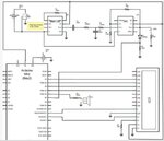
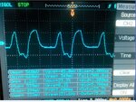
Hello everyone, I am using the attached circuit schematic to get ECG signal, Instead of getting ECG signal, the output looks like as in the attached image, the output signal is taken at the node between R2(100k) and R5(100k) after the low pass filter. The PQRS peaks are not comprehendable. The instructable I am following gets a clean ECG. Is there a possibility that the oscilloscope power noise is being coupled. Any Help would be appreciated. here is the link to the instructable I am following:
https://www.instructables.com/id/Electrocardiograph-Heart-Rate-Monitor/
 

Attachments

  • Circuit schematic.JPG
    Circuit schematic.JPG
    47.7 KB · Views: 70
  • output signal.jpg
    output signal.jpg
    72.6 KB · Views: 67

I'm not sure that the picture shown at that link above was really obtained with a circuit so simple like that. In general, the ECG electronics required for that application embodies a lot of analog circuits, and also perform by hardware mathematical combinations of several “sensors”, each one having their own minumum amount of signal conditioning components. I'm more inclined to believe that the author of this article may have been not measured directly in the human body, but used some ECG simulator, whch is able to electrically generate waves with perfect shapes like that.
 

Many lousy old 741 opamps will not work if the power supply is less than 10V. Its datasheet shows only 30V.
You have the (+) input on the 741 opamp floating with no bias voltage. You also have the inputs of the INA128 floating with no bias voltage.
ECG signals have very low frequencies. The value of your coupling capacitor C1 (10nF) is so low that it blocks low frequencies. You DO NOT want this capacitor.

Why didn't you look at the ECG amplifier schematic in the datasheet of the INA128? It has two opamps that feed a low impedance signal to the shield of the cable and right leg of the patient that cancels interference pickup and biases the inputs.

EDIT: Many Instructables are written by 10 years old kids who know NOTHING about electronics.
 

Attachments

  • ECG amplifier.png
    ECG amplifier.png
    28 KB · Views: 72

The signal appears to be excessively filtered. The peaks are rounded and the QRS complex is barely resolved. First you check the electrodes (Use KCl solution mixed with agar or gelatin) and use copper electrodes (or brass nickel plated; Al has an oxide layer that acts as a rectifier). Play with the low pass filter at the final output. Remember that you are handling source voltages that are typically 1mV or so...
 

I cannot read the tiny writing on the schematic. Maybe the original project has the 7805 regulator and its battery drawn wrong and connected "backwards" and is making -5V? Then the instrumentation amplifier and opamp will have a positive and negative supply, and the Instructables project says the patient is grounded which will bias the instrumentation amplifier. But nothing cancels hum and interference and the highpass and lowpass filters overlap their frequencies and cut the frequencies of a heatbeat.
 

Status
Not open for further replies.

Part and Inventory Search

Welcome to EDABoard.com

Sponsor

Back
Top