Continue to Site

Welcome to EDAboard.com

Welcome to our site! EDAboard.com is an international Electronics Discussion Forum focused on EDA software, circuits, schematics, books, theory, papers, asic, pld, 8051, DSP, Network, RF, Analog Design, PCB, Service Manuals... and a whole lot more! To participate you need to register. Registration is free. Click here to register now.

[Moved] doubt regarding relay connection

Status
Not open for further replies.

bobdxcool

Member level 5
Joined
Mar 9, 2012
Messages
82
Helped
0
Reputation
0
Reaction score
0
Trophy points
1,286
Activity points
2,042
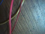
i am doing a project on room light controller using 8051..
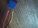
i am using a pcb relay for controlling the light..
i have a doubt regarding the relay pins....


i have a doubt regarding which are the coil terminals and which terminals are nc ,no and common!!

i am posting a picture of it! pls help!! snapshot002.jpgsnapshot001.jpgsnapshot004.jpg
 

You can use an ohmmeter to check the pins

I suppose you know the operation of NC and NO pins
**broken link removed**
 

Give a man a fish and you feed him for a day. Teach a man to fish and you feed him for a lifetime.
Chinese Proverb

If the OP learns how to identify the relay pins on his own he will never have to ask about a relay pinout again...

Alex
 

You can use an ohmmeter to check the pins

I suppose you know the operation of NC and NO pins
**broken link removed**

so sir i should basically use an ohmmeter and connect it across the terminals to see if i get 100 ohm resistance which means the terminals are coil terminals
then for no and nc...i should connect 12 volt supply to the coils and measure resistance at other pins ...the pair which has high resistance is the no and common pair...and other one is nc.

am i right sir??
 

Your description is correct.

The pins that have resistance are the coil pins.
From the remaining three pins one is common and will be shorted to the Normally Closed pin when you have no voltage applied to the relay while the common with the Normally Opened pin will be shorted when you apply voltage to the coil and the relay changes state.

The voltage applied in the relay coil depends and should match the relay rated voltage.

There is of course the alternative of checking the relay pinout in the datasheet of your device if the model number is known.

Alex

thanks a lot sir!
mine is a 12 volt relay so i mentioned 12 volt..
will check ..
actually i am trying to connect this relay to my project automatic room light controller with visitor counter using 8051 ..

here i am connecting the collector of a transistor( bc 547) from my counter circuit to one of the coil terminals...i am connecting a 12 volt supply to other end of coil..
i am planing to control a 240 ac power supplied bulb..
i am connecting one end of bulb holder to no pin of relay and other end of bulb holder to the ac power socket along with the common terminal of the relay!!
 

So you are basically using a circuit like
**broken link removed**

Don't forget the diode and base resistor.
 
@alex-sir i found out the pins of the relay and soldered wires to the pins directly...i have soldered normal thin dc wires to the coil terminals which are going to be connected to the breadboard..
i have used normal thick ac wires for no and common terminals which will go the bulb and ac supply..
i am uploading a pic of the wires used...please correct me if wires used for coil are not proper..


the blue and red wires are normal dc wires connected to coils...n pink n yellow ones ar ac ones.
 

Attachments

  • snapshot007.jpg
    snapshot007.jpg
    19 KB · Views: 52
  • snapshot008.jpg
    snapshot008.jpg
    17 KB · Views: 53

Your coil wires are fine, the coil only uses about 30-50mA so the wires width doesn't matter.

Use an insulating tape to cover the mains connections for security so that you don't touch them.

---------- Post added at 15:20 ---------- Previous post was at 15:19 ----------

I hope you have wired a switch before right?
don't connect both mains wires to the relay and short circuit them..

no sir...one ac wire from common will go directly to the socket...other ac wire from no of relay is connected to one terminal of a bulb holder...other terminal of the bulb holder will go to other pin of ac socket..
i am connecting the 2 bottom pins of the 3 pin ac socket!
correct me if i am wrong!
 

You will leave it unconnected, when the relay is off the common and NC are connected together which would connect the ground to your mains cable, you don't want that.
 

@alex:thanks a lot for your help!!

my project automatic room light controller with counter is working like a gem!!
will post a video soon!!
 

Status
Not open for further replies.

Part and Inventory Search

Welcome to EDABoard.com

Sponsor

Back
Top