Continue to Site

Welcome to EDAboard.com

Welcome to our site! EDAboard.com is an international Electronics Discussion Forum focused on EDA software, circuits, schematics, books, theory, papers, asic, pld, 8051, DSP, Network, RF, Analog Design, PCB, Service Manuals... and a whole lot more! To participate you need to register. Registration is free. Click here to register now.

[MOVED]Design with Eagle quad-Op-AMp

Status
Not open for further replies.

denver56

Member level 3
Joined
Mar 18, 2012
Messages
67
Helped
0
Reputation
0
Reaction score
0
Trophy points
1,286
Activity points
1,725
Hi people ! I'am new to the world of electronic but i have a work for the university to do : design for 60 channels the following circuit with EAGLE:


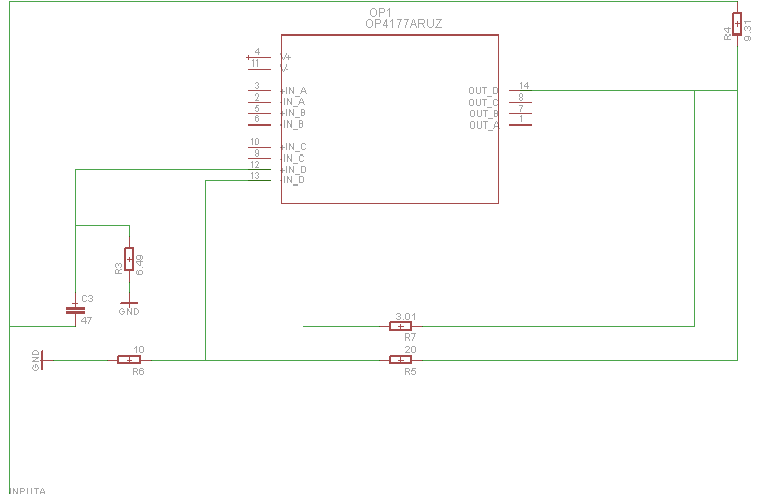
I want to realize a little board (max 4x3,15 inch) so i was thinking to use a quad-opamp (so : 2 opamp for every channel (as you see from the image) = 30 quad-opamp)

Now the problem is the space : someone can help designing just one of these quad-opamp with his relative capacitors/resistors ??

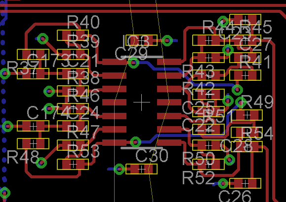
This is what I made :-(


Thank you all , people !!!!!!!!!!!
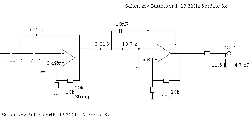
 
Last edited:

Re: Design with Eagle quad-Op-AMp

Your schematic symbol looks really ugly. Eagle has plenty of library components, inluding quad OPs with identical pinout. You should have an idea about resistor and capacitor package sizes available for your project. And don't forget power supply bypassing.
 

Re: Design with Eagle quad-Op-AMp

Your schematic symbol looks really ugly. Eagle has plenty of library components, inluding quad OPs with identical pinout. You should have an idea about resistor and capacitor package sizes available for your project. And don't forget power supply bypassing.

well, unfortunately I have to use exactly that quad-opamp (is this a real problem ??? ). About resistor only the value is important... what do you mean about "power supply bypassing" ?? THANK YOU VERY MUCH !!!
 

Re: Design with Eagle quad-Op-AMp

Isn't it easier to rename an OP existing already in the library that has the same pinout?
 

Re: Design with Eagle quad-Op-AMp

mmm every opamp has his own specific parameters... if i change the models , i change those parameters ... Moreover, what do you mean with "quad OPs with identical pinout" ? can you give me an example? THX
 

Re: Design with Eagle quad-Op-AMp

There are no "models" in Eagle - it is a schematic capture and layout package. Any part with the same pinout and package will do.

You need to make sure you schematic is drawn accurately before you start. You have junction nodes where there are no junctions and no junction nodes where there should be. Run the ERC.

Decoupling capacitors should be across the power rails of each IC.

Keith
 

By using a standard OP symbol, you get the option to draw your schematic copying the prototype scheme part by part. This should help you in gettings things right. It would be a good idea to use right capacitor and resistor values from the start.
 

what do you think about these schematic /board that I made ? Why autorouting command doesn't create via for the opamp?? MAny thanks ! 1.png2.png
 

It is awful. The point of a schematic is to show what the circuit does. That is why multiple opamps are drawn as separate opamps even when they are in the same package. There are plenty of standard symbols in the libraries without creating your own for basic devices like quad opamps. Your 'opamp' symbol has the pins separated from the device. You have junctions where they aren't needed.

Autorouters take some skill an knowledge to set up. I wouldn't use one for a circuit like that. Manually route it.

Keith
 

One high pass capacitor is missing, also OP power supply.

You should also observe the suggestion about bypass capacitors:
Decoupling capacitors should be across the power rails of each IC.

The component arrangement is far from beeing optimal. If it follows the filter topology more closely, trace length and number of crossing can be reduced.

Obviously, a design with the presently selected components can never fit the required board size. A simple estimation shows, that you have about 0.5 x 0.8" for a dual channel. SMD parts are absolutely required, chip size 0805 should most likely work, 0603 is more easy.
 

in order to achieve an ordinatic schematic i was thinking to separate the in/out pin of the opamp from their components (resistors and capacitors). Do you know how to di it ? i was thinking to name the wire of the components ... any idea ?? thank you very much !!
 

ok ! I was using the trial version XD. Another problem : what you think about putting power tracks (+5 -5 V) on top side and putting a ground polygon on the bottom side ? Is that a good idea in order to minimize noise ? THX !
 

ok ! I was using the trial version XD.

I guess you are answering Keith' question in your other thread.

what you think about putting power tracks (+5 -5 V) on top side and putting a ground polygon on the bottom side ? Is that a good idea in order to minimize noise ? THX !
I would usually go this way for a two layer analog SMD circuit. Flooding the bottom with ground and additionally allow short routes that don't cut the ground continuity.
 
mmm there are analogical tracks also on the bottom layer... could be this a problem ?
 

The only problem is the ground net topology, it should be continuous somehow.
 
so your advice is supply+signals on the toppome. Ground polygon on the bottom. Right ?

- - - Updated - - -

Someone can help me roting this pcb ? I have no more empy space XD Any advice ? THX !
 

Attachments

  • pcb.in-out.zip
    19.6 KB · Views: 57

ok people. That's a sample of my pcb. What do you think about it ? More in detail, what do you think about decoupling capacitor (C29 for V+ and C30 for V-)? Should they be more close to their respective pin or is it ok?


Status
Not open for further replies.

Part and Inventory Search

Welcome to EDABoard.com

Sponsor

Back
Top