Continue to Site

Welcome to EDAboard.com

Welcome to our site! EDAboard.com is an international Electronics Discussion Forum focused on EDA software, circuits, schematics, books, theory, papers, asic, pld, 8051, DSP, Network, RF, Analog Design, PCB, Service Manuals... and a whole lot more! To participate you need to register. Registration is free. Click here to register now.

[Moved] battery monitoring using pic

Status
Not open for further replies.

scd

Newbie level 4
Joined
Jun 15, 2011
Messages
5
Helped
0
Reputation
0
Reaction score
0
Trophy points
1,281
Activity points
1,326
how to i monitor battery voltage and current using pic18f4321's adc? basically, i want it as 10% ,20% etc charged.. thanks in advance!!
 

Re: battery monitoring using pic

This depends on the battery technology. Every technology has its own behaviour. The most basic (but unacurate) method is measuring only the battery voltage. If you use lead acid batteries, following charts will be useful:
https://www.scubaengineer.com/documents/lead_acid_battery_charging_graphs.pdf

---------- Post added at 14:44 ---------- Previous post was at 14:40 ----------

To measure the voltage you can make a resistor voltage divider.
 

Re: battery monitoring using pic

I suggest measuring the current too. But this may need the use of an opamp to amplify/scale the voltage drop on the current sensing resistor which usually has a low value.
From the measured current (at specific intervals), one can also calculate the charging or discharging electrical charges (capacity):
Q = I*t

And if you will be able to save V vs. Q (in a memory to be displayed later) you will get a good idea on the real characteristics of your battery after a few charging-discharging cycles. But as you known these characteristics will depend on many factors. Temperature is one of them. And the way (current vs. time) in which the battery is charged and discharged will likely give different efficiencies (discharging power/charging power) or (discharging capacity/charging capacity). But for rather similar conditions, you will get useful curves though with time they tend to shift too, as the battery gets older ;)

Later, you may like to monitor also the internal resistance of the battery which gives a good sign on its age or health :)
A fresh battery has a relatively very small internal resistance which will increase with time (and it is also affected by some other conditions).

Kerim
 
  • Like
Reactions: scd

    scd

    Points: 2
    Helpful Answer Positive Rating
Re: battery monitoring using pic

12 Volt battery
oran Volts per Cell

100% 12.70 2.12
90% 12.50 2.08
80% 12.42 2.07
70% 12.32 2.05
60% 12.20 2.03
50% 12.06 2.01
40% 11.90 1.98
30% 11.75 1.96
20% 11.58 1.93
10% 11.31 1.89
0 10.50 1.75
*********************************
Ah/saat
C/3 charge rate --> 75% recharged
C/5 charge rate --> 85%
C/10 rate --> 90%
C/20 rate --> 95%
C/100 rate --> 100%
************************************
 

Re: battery monitoring using pic

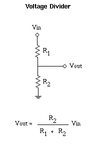
To monitor a larger voltage than yout ADC can handle, you'll need to reduce the voltage amplitude by some known factor. That is done with a simple voltage divider. Most PIC's only handle +5V max, so a simple scale factor would be to take a maximum of 15V and reduce it to 5V, a factor of 3:1.

The basic two-resistor voltage divider uses the following equation Vout = Vin * R2/(R1+R2).
voltage-divider.gif
If you make R2 = 10k ohms, then R1 will need to be 20k ohms (plug the numbers into the equation to see how it works).

Now you can connect Vout to the input of your ADC without fear of over-volting the ADC. I'd also add a 1k resistor in series between Vout and the ADC pin. Since the ADC is a high-impedance input (draws very little current), the votlage drop across the 1k resistor will be negligible. This will help protect the ADC in case something goes wrong on the input circuit (can't draw excessive amounts of current). Additionally, you could hang a 4.7V zener diode in shunt to ground on the ADC pin, which would act as an overvoltage clamp, and help prevent you from destroying the ADC circuitry in the event over overvoltage on the pin.
 
  • Like
Reactions: scd

    scd

    Points: 2
    Helpful Answer Positive Rating
Re: battery monitoring using pic

thanku all.. bt i also want to monitor battery capacity.. tht can b done by finding current - ampere hours..
 

Re: battery monitoring using pic

You may monitor the rate of voltage increase (correlated to charge rate) as a function of input current to calculate the capacity.
Example: if charge current is constant 1 A and you measure a 30% (1.96 V per cel) to 40% (1.98 V per cel) increase in 1 h then the capacity would be approximately 1 A* 1 h / (40%-30%) = 10 Ah...
 

Re: battery monitoring using pic

thanku all.. bt i also want to monitor battery capacity.. tht can b done by finding current - ampere hours..

Read this, should give you some good direction on what you need to monitor.
 

Re: battery monitoring using pic

Hi everyone and sorry for bumping this thread. I need to monitor battery current up to 50 Amps. I have the solution for it and which is using a current sense resistor / shunt resistor. I want to make my own shunt but if i go for copper wire then its gauge vs length, the shunt will be too big. Can i use other easily available materials to make shunt which have high resistivity and low temperature constant?
 

Re: battery monitoring using pic

Perhaps you may like to look fo wires (I forgot their names since there are different alloys) that are used in heaters... But as a shunt you don't need to choose a gauge that lets the wire (or wires in parallel) not be hot @50A, since here it is not meant to heat anything.

Once I faced this problem, I just bought a low cost mechanical current-meter (scale 50 A) and used its shunt :grin:
By this way, I had a display and a shunt for my controller.

Edited.
 
Last edited:

Re: battery monitoring using pic

Thanks for the reply. I forgot to mention that i need exactly 0.1 ohm shunt for 5V drop @50A. The shunts for ammeter has a very low resistance like 0.005 and like that. So if i m going to use ammeter shunt then i have to put a cut in it until it become 0.1 ohms. also i have heard that if shunt temperature goes above 150 degrees then its resistance changes permanently. so by putting a cut in it will increase the resistance but will it increase its temperature? i think the gauge at that cut will obviously be low but also temperature at that point will be high also.
 

Re: battery monitoring using pic

Oh... I see.
So you look to build a low-temperature small heater:
P = 5V * 50A = 250 W

The practical choice could be then to find suitable heating wires and parallel short pieces of them so that their temperature @50A won't increase appreciably.
I am not expert in this field but among what I have found, the following tables may give a hint (it seems there is a small program too but I didn't run it yet):

**broken link removed**

Kerim
 

Re: battery monitoring using pic

Thanks for the reply. I forgot to mention that i need exactly 0.1 ohm shunt for 5V drop @50A. The shunts for ammeter has a very low resistance like 0.005 and like that. So if i m going to use ammeter shunt then i have to put a cut in it until it become 0.1 ohms. also i have heard that if shunt temperature goes above 150 degrees then its resistance changes permanently. so by putting a cut in it will increase the resistance but will it increase its temperature? i think the gauge at that cut will obviously be low but also temperature at that point will be high also.

5V @ 50A = 250 watts of heat (that's like 4 60 watts light bulbs!!). Your current shunt will be wasting a LOT of power.

If I were you, I'd go with a MUCH smaller current shunt (like the 5 milliohm you mentioned... that'd dissipate (50^2)*0.005 = 12.5 watts of heat). Run the differential voltage from the current shunt through an instrumentation amplifier (can be made from op-amps), to scale it back to a usable range. That's how we monitored our solar cell array, battery and motor currents on the electric vehicle team I was on in college. The output voltage from the op-amps was fed directly into the ADC on a PIC microcontroller (0-5V range).
 
Last edited:

Re: battery monitoring using pic

Thanks for the reply but i m not building a heater. I m building a big battery charger. I m fast charging SLA batteries. Some people here are still sticking with old concepts of battery charging but there are new fast charging algorithms on the web now. previously i made 12 amp ,3 stage charger and i experimented it on a 12 Ah battery for 6 months. battery is still healthy. Now i need shunt to have precise amount of constants current that is why i can't use those golden type 0.1ohm resistors.

https://www.edaboard.com/threads/217606/

Have a look here and u will understand. and comment there for my solution. thanks for your time.
 

Re: battery monitoring using pic

what would be range of voltage between the charging and discharging points ie could you please tell the calibration in terms of percentages ie " voltage level - percentage of charge left in battery "

Thank You
 

Re: battery monitoring using pic

Thanks for the reply but i m not building a heater. I m building a big battery charger. I m fast charging SLA batteries. Some people here are still sticking with old concepts of battery charging but there are new fast charging algorithms on the web now. previously i made 12 amp ,3 stage charger and i experimented it on a 12 Ah battery for 6 months. battery is still healthy. Now i need shunt to have precise amount of constants current that is why i can't use those golden type 0.1ohm resistors.

https://www.edaboard.com/threads/217606/

Have a look here and u will understand. and comment there for my solution. thanks for your time.

You can use 0.1 ohm resistors, IF...
1) they can handle the dissipated power without melting or annealing, and...
2) you can handle the voltage dropped across the current shunt

For power in a resistive device, the equation is
mimetex.cgi
.
http://www.kpsec.freeuk.com/power.htm

At the maximum current, power dissipated = (50^2)*0.1 = 2500*0.1 = 250 Watts. Show me what 0.1 ohm resistor you'd like to use that can handle that much dissipated power, and your welcome to try it.

Also, recall Ohms law... V = I*R. The voltage dropped across your 0.1 ohm resistor will be 50*0.1 = 5V. So your ~14V charging voltage will drop to 9V at the battery terminals. Or, to keep ~14V on the battery terminals @ maximum current, the power supply will need to be 14+5 = 19 volts @ 50 amps, just to overcome the loss in the current shunt.

Those two reasons are why you should avoid such a high resistance current shunt, and use something in the milliohms region.
 

Re: battery monitoring using pic

hi sohail here i m doing project on lead acid battery, title of my project is "Develop an algorithm to estimate the state of health of lead acid batteries"
i need ur help regarding this.
sohail zaman

Raisalpur
 
Last edited by a moderator:

Status
Not open for further replies.

Part and Inventory Search

Welcome to EDABoard.com

Sponsor

Back
Top