Continue to Site
Follow along with the video below to see how to install our site as a web app on your home screen.
Note: This feature may not be available in some browsers.
unsigned char FlagReg;
sbit ZC at FlagReg.B0;
int x;
void interrupt()
{
int i;
if (INTCON.INTF)
{ //INTF flag raised, so external interrupt occured
// ZC = 1;
INTCON.INTF = 0;
// }
//if (ZC){ //zero crossing occurred
for(i=1;i<=x;i++)
{
delay_ms(1);
}
PORTD.B0 = 1; //Send a pulse
delay_us(250);
PORTD.B0 = 0;
//ZC = 0;
// }
}
}
void main() {
x=1;
PORTB = 0;
TRISB = 0x01; //RB0 input for interrupt
PORTA = 0;
ADCON1 = 7; //Disable ADC
TRISA = 0xFF; //Make all PORTA inputs
PORTD = 0;
TRISD = 0; //PORTD all output
OPTION_REG.INTEDG = 0; //interrupt on falling edge
INTCON.INTF = 0; //clear interrupt flag
INTCON.INTE = 1; //enable external interrupt
INTCON.GIE = 1; //enable global interrupt
while (1)
{
if((RC5==0))
{
x=x+1;
//delay_ms(1);
}
if((RC6==0))
{
x=x-1;
//delay_ms(1);
}
}
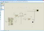
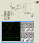
}Did you see the link I posted in post #7. How many steps do you need. Is 10 steps of power control enough ? Are you simulating in Proteus or testing in hardware. Please provide the circuit.
Should the least power turn of the device or do you want another button to turn ON/OFF the device ?
What is your AC frequency ? 50 Hz or 60 Hz ?
Code C - [expand]
Code C - [expand]
Code C - [expand]
Code C - [expand]
@betwixt
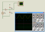
Please check the code I have attached. If you have Proteus then please check why TRIAC signal is not showing.