rwind
Newbie level 1
Hi,
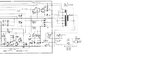
attached is the circuit diagram of a old Pioneer receiver SX 1500. I am planning to reuse the transformer. In the picture (the thick black lines on the right top) pin 11 seems to be center tap and 13 and 9 are the other 2 ends of the winding. Between 11 and 13/9 I measure 33 V. But I don't need 33 V, all I need is about 18V which is what I measure between 12/10 and 11 the center tap. The fuse rating for the old amplifier says 2.5 A and is designed for about 100 W.
When I measure the resistance between 13 and 12 it shows almost as short, it looks like they are connected.
Can I use 12/10 with 11 for the PSU for a 50 W amplifier?
Thanks