Continue to Site

Welcome to EDAboard.com

Welcome to our site! EDAboard.com is an international Electronics Discussion Forum focused on EDA software, circuits, schematics, books, theory, papers, asic, pld, 8051, DSP, Network, RF, Analog Design, PCB, Service Manuals... and a whole lot more! To participate you need to register. Registration is free. Click here to register now.

Motor current testing

Status
Not open for further replies.

vishjay

Member level 2
Joined
Feb 1, 2019
Messages
42
Helped
0
Reputation
0
Reaction score
0
Trophy points
6
Activity points
306
Hi all,
I know it is a small question but when i tried i didnt get it. So i just want to make sure whether i did any wrong test.

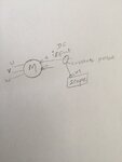
How to measure the input current of my stepper motor? During the movement of motor i connected current probe and didnt get how i want? Can anyone tell me please.

Thanks
 

If your motor is being driven by pwm then use scope on one shot mode
to capture waveform of current consumption. Also what is the current
probe G, in Volts/Amp ? What is its bandwidth ?


Regards, Dana.
 

What's the motor configuration (bipolar or unipolar, half or full step, voltage or current driven, use pwm)?

Which current do you probe, what do you expect, what do you see?
 

Motor is driven varying voltage (voltage mode).
Well it runs with pwm control .
I just want to see the input current waveform using current probe connecting with scope. How are the connections should be?
 

Hi,

Where do you see a problem?
Connect the probe at the node with the current, ... and if you want to see the waveform, then use a scope..

Klaus
 

Thabks klaus
i put the motor‘s positive wire in the current probe and one end of the probe connected to scope. But during the motor movement the input current in the power supply shows 3Amps but in the scope waveform shows something like 1Amp
Did i connect the set up correctly?
 

Hi,

and one end of the probe connected to scope.
What dies this mean? Every measurement needs two wires...

Draw a sketch or take a photo.

Klaus
 

Hi,


What dies this mean? Every measurement needs two wires...

Draw a sketch or take a photo.

Klaus
I mean one end of current probe.
 

Attachments

  • C71537C2-84A5-4252-A663-A51C42E3ADB4.jpeg
    C71537C2-84A5-4252-A663-A51C42E3ADB4.jpeg
    532.2 KB · Views: 69

Hi,

O.K. your motor has DC supply as well as three phase AC supply.

Never seen such a thing.

Klaus
 

Hallo,
Three phase Ac is output.
Input is DC supply
It is a brushless dc motor

Thanks
 

Hi,

The round symbol with an "M" inside usually is a motor. But a motor has no electrical output.

In first post you talk about a stepper motor... now you talk about a brushless DC motor.

I'm really cinfused ... inseveral ways. This makes it impossible to help.
****
Thus I'd say it's time for you to give some useful informations:
* a photo of your complete wiring
* the motor vendor and exact part number. Best if you can give a link to the datasheet.
* vendor and type of your current probe
* vendor and type of the motor driver unit.
* and so on...

Klaus
 

Status
Not open for further replies.

Similar threads

Part and Inventory Search

Welcome to EDABoard.com

Sponsor

Back
Top