jegues
Member level 3

- Joined
- May 29, 2011
- Messages
- 58
- Helped
- 0
- Reputation
- 0
- Reaction score
- 0
- Trophy points
- 1,286
- Activity points
- 1,915
Evening gents,
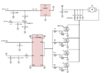
Attached is schematic of a motor controller I am looking to modify and implement.
As a start, I've been reading through the datasheets of the IC's and began looking the the external resistors and capacitors to try and figure how the particular R and C values were selected.
1)I started with the string of three resistors at the output of the LM7805. This string of resistors gives a voltage value between 0.202-4.79V at the top of C2 depending on the position of the wiper. Is there any particular reason a value of 202Ω is moreso convenient than any other resistor value?
2)Can someone help me clarify what the role of R4 and C2 is? From the terminals of the microcontrollers ADC pin it looks as though it is a LPF, with a cutoff frequency of,
\[f_{3dB} = \frac{1}{2 \text{pi} R_{4} C_{2}} = 3.39Hz\]
3) Is R7 (the 4.7kΩ resistor on the input pin of the MOSFET gate driver) for limiting the current to ground in the event of a short or fault on either side of it?
4) Again we see what seems to be an RC LPF looking from the enable pin of the gate driver outwards, is that what this circuit is for? Here I calculate a cutoff frequency of,
\[f_{3dB} = \frac{1}{2 \text{pi} R_{5} (C_{3}+C_{4})} = 3.60Hz\]
5) Moving over to the output portion of the gate driver we see voltage dividers across the gate-source junctions of the MOSFETs.
From the datasheet of the gate driver, we note that VOH=Vcc-0.025 = 11.98V, and from the voltage divider formed by the 30Ω and 100kΩ resistors we find that,
\[V_{GS} \approx 11.98V\]
6) If we assume Vss = 72V, and that C5 is constructed by a parallel string of twelve 470uF caps, how do I go about figuring out the drain current through each MOSFET? Also, why is the string of twelve 470uF caps needed?
7) It has also been suggested to me that some 22kΩ safety resistors should be added from the gate of each MOSFET to ground in the event that the gate driver fails.
It was mentioned that the MOSFETs gate voltage would drop to around 5-7 volts if the driver quit working, keeping the MOSFETs on until they burn out. How do they figure that the gate voltage will be 5-7 volts?
Thanks again for all your help!