Continue to Site

Welcome to EDAboard.com

Welcome to our site! EDAboard.com is an international Electronics Discussion Forum focused on EDA software, circuits, schematics, books, theory, papers, asic, pld, 8051, DSP, Network, RF, Analog Design, PCB, Service Manuals... and a whole lot more! To participate you need to register. Registration is free. Click here to register now.

Most noise free way to carry high speed serial bit streams

Status
Not open for further replies.

cupoftea

Advanced Member level 5
Joined
Jun 13, 2021
Messages
2,588
Helped
54
Reputation
108
Reaction score
115
Trophy points
63
Activity points
13,587
Hi,
Is the attached differential signalling?
Does it need 4 wires or 3, or 2?
...ie , just the two signal wires, or each signal wire twisted with ground, ie 4 wire.

LTspice and jpeg attached

Differential signalling_.jpg
 

Attachments

  • Differential signalling_.zip
    1.9 KB · Views: 117

It appears to be, but looks pretty slow and crappy - no line termination,
slow op amp buffers (which may hide some of the inevitable ringing)
etc.

Note says two grounds are required. Why? TX side, the grounds are
common (by symbol-tie).
 
Note says two grounds are required. Why? TX side, the grounds are
common (by symbol-tie).
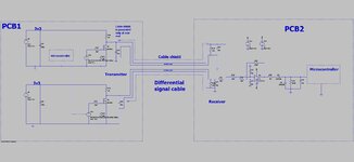
Thanks yes, each of the two signals needing a ground for twisted pairing.

i don't see a cable (transmission line) in the simulation circuit. In so far a no-question.
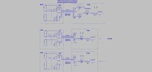
Thanks, you mean an "LCLCLCLC" type thing for the distributed L and c of the txmission line?
Please just pretend that it is there.
 

The two signal lines should be twisted about each other for HF CM noise,
a common shield and then select a line snubber / terminator (AC coupled?)
that makes signal "clean enough".
 
Hi,
This concerns finding a way of carrying high speed serial bit streams between PCBs with as little noise problems as possible.
So many co’s have trouble with this, that its necessary to go back to first principles, and draw out the TxRx circuitry as attached.

The bottom diagram is the most noise immune way to carry a high speed signal from one PCB to another. This is because there is edge slew rate management via the RC’s. Also, the receiving comparators have small caps at their input terminals. Also, there are termination resistors at each end of the cable. Also, the cable is shielded and grounded at only one end.

Also, there is attention payed to whether the signal is getting diminished too much by the potential divider effect of the RC resistors and the termination resistors.

Also, the rails of the receiving comparators are well beyond the received signal voltage level…..so there wont be problems with input signals going outside the receiving comparators input rails. This is especially useful because the ground potential at each PCB may be slightly different.

Also, there is minimisation of area within current loops. -As such, there must be 4 wires, ie, each diff signal with its ground return. If not done like this then current loops are simply too large.
Do you agree, the attached is the best way?

LTspice simulation, and PDF schem, attached.

Differential signalling_.jpg
 

Attachments

  • Differential signalling_1.zip
    4.1 KB · Views: 106

Thanks, here i am referring to electrical comms.
As such, i believe what is needed now is "common sense comms"....not all this "balanced signalling", " differential signalling", etc etc.....a look at the circuit that produces the comms......the setting of references in Rx comparators.....even CAN isnt that good with the minimum signal levels , and too high slew rates.
 

You keep saying that you are looking for “as little noise problems as possible.” I have told you what that system is.

Taking a differential pair and then separating the pair and twisting the individual wires with grounds makes zero sense-you’re defeating the whole common-mode rejection ability of diff pairs.

Differential signaling has been around for a long, long time. And it works. For some reason you’re acting like you’re the first person to ever need to send a signal.
 
i believe what is needed now is "common sense comms"....not all this "balanced signalling", " differential signalling", etc
You can believe what you want, but your "common sense comms" are not going to give the results you want in a real system. :rolleyes:
If you want to know how it's done in the real world, look up how HDMI or high-speed Ethernet signals are sent.
 
Taking a differential pair and then separating the pair and twisting the individual wires with grounds makes zero sense-you’re defeating the whole common-mode rejection ability of diff pairs.
Thanks, in that case, the twisted diff pair has to get twisted with the ground.
There is undeniable return ground current from each diff signal , back through ground...so the area of that current loop has to be made as small as possible.
Perhaps better still the ground could be like in the outer bit of a coaxial cable, encircling the twisted diff pair.
Ground much connect between the PCBs any way because the PCBs are grounded to the same potential.

As you know, sending just the twisted diff pair is not possible......a ground has to go aswell so that both PCBs are both grounded tot he same potential.....and then you have to mind the area of that diff signal__ground loop.

There is no choice in this, i believe many would agree?
As attached shows a single ground return with the diff pair.....

I dont see why a two twisted pairs of signal and ground can't be twited together...then its the best of both worlds................looking after current loop area, as well as getting the diff sigs close together...

If you want to know how it's done in the real world, look up how HDMI or high-speed Ethernet signals are sent.
...thanks, i believe that my method agrees with ethernet...if you see point 6 of the following...


...it says..
Ensure a solid ground plane is present beneath the differential signals for the return path. Never route signals over the split plane as that may cause EMI.

...As such, they agree that its just as important that each trace of the diff pair is just as near to ground, as it is to the other diff signal in the pair.......the return current of each diff signal returns via ground...not via the opposite signal in the diff pair....i beleieve that most comms tutorials completely overlook this crucial factor.
--- Updated ---

Page 6, Fig 11.1a of the following.....

file:///C:/SMPS%20Course_SMALL_H67/Course%20Folders_SMALL/comms/RS485%20elec%20sigs%20_slla272d.pdf

...shows just why a diff signalling comms link cannot just use the two diff pair signals in its comms link......it confirms that the return current of each diff signal is via the ground....and points out that there is a massive loop created via this return current.

.....they then try and solve it with 11.1b....but then end up with a big ground loop...but that is better than 11.1a.

In Fig 11.2 they solve the whole thing by using isolated signalling.......which shows that isolation is often key to solving noise issues in comms, and not things like "differential signalling"....diff signalling comes a cropper in 11.1a and 11.1b, and even 11.1c...as can clearly be seen.
 

Attachments

  • Differential signalling_2.zip
    5.6 KB · Views: 96
  • Differential signalling_2.jpg
    Differential signalling_2.jpg
    167.6 KB · Views: 98
Last edited:

As you know, sending just the twisted diff pair is not possible......a ground has to go aswell so that both PCBs are both grounded tot he same potential.....and then you have to mind the area of that diff signal__ground loop.

There is no choice in this, i believe many would agree?
“As I know” sending just the diff pair is completely possible. It’s done ALL THE TIME. A ground does NOT ‘have to go as well’.
 
There's no clear determination of "high speed" in this thread. With the used OP, the circuit is relative slow and particularly lacking suppression of fast common mode interferences.

Industry standard wiring of differential signals has been already explained. RS-422 driver/receiver are suitable up to several 10 MHz. For high noise level environment, common mode termination in combination with common mode chokes may be necessary.
--- Updated ---

Voltage and current of differential signal lines adds to zero, therefore no return path is required as such. If the receiver isn't galvanically isolated, it has nevertheless limited common made range, you need a common ground to satisfy it.
 
Last edited:
woops sorry, midway through #11 i am referring to this article...

“As I know” sending just the diff pair is completely possible. It’s done ALL THE TIME. A ground does NOT ‘have to go as well’.
...Page 6, Fig 11.1 of this
..shows that the ground is used as a return by each differential signal. As such, ground should go closely alongside each differential signal. (to reduce the current loop area)

Voltage and current of differential signal lines adds to zero, therefore no return path is required as such.
...Thanks, just noticed this, will trace out the currents in the loops to see it. It seems strange that if the current sums to zero, why then is slla272d above going on about ground return current in page 6, fig 11.1?
 
Last edited:

...Page 6, Fig 11.1 of this
..shows that the ground is used as a return by each differential signal. As such, ground should go closely alongside each differential signal. (to reduce the current loop area)
No. That is not what that diagram is showing. It is showing that a difference in ground potential in the two different systems manifests itself as a common-mode offset. There is NOTHING in the diagram or the text that says you need a ground return for the differential signals. Nor is there anything in the document saying you should run ground “closely alongside each signal”. Or run ANY ground.
 
Start by telling us the distance it has to bridge and how fast 'fast' is. I regularly send data streams at speeds > 100Kb/s over unscreened CAT-5 cable and distances > 50m with no ground link at all except for both ends having their own ground to the wall socket earth pin.

As FvM pointed out, this is simple with RS-422. My sender/receiver of choice is an ADM488 (=MAX488) at each end. It is MUCH simpler than the arrangement you posted and a fraction of the cost.

Brian.
 
There is NOTHING in the diagram or the text that says you need a ground return for the differential signals
Thanks, page 11 , section 11 states...

"relying on the local earth ground as a reliable path for the return current is dangerous"

...that suggests they are speaking about a ground return current
 

Voltage and current of differential signal lines adds to zero, therefore no return path is required as such
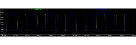
Thanks, the attached shows differential signalling, and the currents do not sum to zero, as the waveform shows...the shown currents are the currents in each differential signal wire.
 

Attachments

  • diff pair signal currents.jpg
    diff pair signal currents.jpg
    92.1 KB · Views: 102
  • Differential signalling_3.zip
    2.1 KB · Views: 91
  • diff signalling.jpg
    diff signalling.jpg
    161.5 KB · Views: 99

If you use a conventional differential transmitter it wont have the gap between the signals.

Normal practice is to use TWO wires carrying inverted signals with respect to each other, twisted to improve coupling between them and if necessary, the receiving end may have some R or RC network to dampen ringing.
Twisting the TWO wires together ensures they follow the same route and are subject to the same interference. When one is inverted and added to the other at the receiver, any common mode interference should cancel. Additionally, radiated signals are minimized because the electrostatic and magnetic field around the two wires should sum close to zero.

A ground isn't essential for screening purposes although there is no harm in using one but the TWO wires should be twisted together inside the shield. Differential signalling works on the principle that the relative polarity between the wires carries the data. Any common voltage on both wires does not matter as long as it doesn't exceed the limit imposed by the receiver.

Brian.
 
Normal practice is to use TWO wires carrying inverted signals with respect to each other,
...Thanks, do you mean the signals in the LTspice sim of post #18 aren't inverted with respect to each other?
..I thought they were the inverse of each other?...ie, when one is hi, other is lo, and vice versa

If you use a conventional differential transmitter it wont have the gap between the signals.
...Thanks, though do you think the dead time i inserted does harm?....the signals will be read in the centre of their "high time"......well away from the dead time bit.
 

Status
Not open for further replies.

Similar threads

Part and Inventory Search

Welcome to EDABoard.com

Sponsor

Back
Top