Continue to Site

Welcome to EDAboard.com

Welcome to our site! EDAboard.com is an international Electronics Discussion Forum focused on EDA software, circuits, schematics, books, theory, papers, asic, pld, 8051, DSP, Network, RF, Analog Design, PCB, Service Manuals... and a whole lot more! To participate you need to register. Registration is free. Click here to register now.

[SOLVED] Mosfet switch to control the signal flow

Status
Not open for further replies.

SJ_ELECTRO

Newbie level 4
Joined
Oct 2, 2017
Messages
5
Helped
0
Reputation
0
Reaction score
0
Trophy points
1
Activity points
51
Dear friends,

I'd like some expert advise on how to pass the signal through a PMOS or NMOS device. I have a signal to be blocked and let through only when I need it. The signal to be controlled is a 5Vpkp sine and I want it to be stopped at particular periods during operation. I have tried some smart advise from youtube guys, but there seems to be a problem, the signal is being passed no matter what the gate voltage is. I used PMOS in my atempt.

regards
 

I have a signal to be blocked and let through only when I need it.
Do you need bidirectional current flow ?

I fear that a floating supply might be needed.
 

I would need unidirectional. I simply want to switch off the flow of the signal in one direction at certain points in time.
 

Then a simple half wave rectifier and a MOSFET could do the job. You need to consider voltage drop of the diode if might or might not be an issue for you.
For single ended load, floating driver is needed, otherwise, not, which is more simple.
 
Hi,

An analog switch like DG201?
A photomos relay?

Klaus
 

I don't want to rectify the signal, I just simply want to be able to control whether its going through a cable or not. There is only one signal which is received from the sonic sensors and just before amplification, I wish to mute the signal path. Basically I want to control when the received signal is going to be amplified and when it will just be ignored.
 

I don't want to rectify the signal, I just simply want to be able to control whether its going through a cable or not.
Yes I know. The diode is there just to prevent current flowing in the reverse direction through the substrate diode of the MOSFET, effectively cancelling it, transforming the MOSFET into a current unidirectional switch, as you said you need.
There is only one signal which is received from the sonic sensors and just before amplification, I wish to mute the signal path. Basically I want to control when the received signal is going to be amplified and when it will just be ignored.
However, as already said, the diode voltage drop might (or might not) be a problem for your specific application. Implementing an "ideal" diode to remove that voltage drop using discrete components does not worth it, so possibly the analog switches ICs presented by the other members might be a better solution.
 

Is the signal pus and minus 2.5Vpk?
If so you will need a switch that can block both polarities, or DC offset the signal so that none of the signal goes negative.

What supply voltages do you have available?
 

Please see the attached.

So I will have this signal (6V pkp) coming from the IC and at some point in time I need to switch it ON/OFF so that the amplifier does not get any signal for a very short period of time, I assume I need some fast switch that can handle switching in micro seconds. However, I am trying to use a PMOS directly to handle this operation. 20180225_211841.jpg
 

I think there was a misunderstanding.

Current unidirectional means it passes only 1 half sinusoid: either the positive or the negative, but NOT both.
Now I think what you want is a switch that blocks both, and passes both (both positive and negative parts of the sine wave), is this right ? If this is right, then you need 2 series switches (2 MOSFETs in series) connected like this:
Sine Wave --> Drain 1 (the arrow "-->" represents electrical connection)
Source 1 --> Source 2
Drain 2 --> amplifier imput
Gates tied together: Gate 1 --> Gate 2

- - - Updated - - -

If so you will need a switch that can block both polarities, or DC offset the signal so that none of the signal goes negative
At the beginning he said he needed current unidirectional, which means one half sinusoidal needs to be blocked always. Seems that now needs to block both.
 
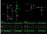
This may or may not work the way you want. The lefthand circuit has a transistor arranged so it conveys the incoming signal only when turned on by a bias pulse.

The righthand circuit does something similar with a diode.
Signal amplitude may need to be attenuated so it does not exceed the diode turn-on threshold.

clock On carries signal thru transistor or diode.png
 

Status
Not open for further replies.

Similar threads

Part and Inventory Search

Welcome to EDABoard.com

Sponsor

Back
Top