Continue to Site

Welcome to EDAboard.com

Welcome to our site! EDAboard.com is an international Electronics Discussion Forum focused on EDA software, circuits, schematics, books, theory, papers, asic, pld, 8051, DSP, Network, RF, Analog Design, PCB, Service Manuals... and a whole lot more! To participate you need to register. Registration is free. Click here to register now.

MOSFET power disspation as a dummy load

Status
Not open for further replies.

Clement10

Newbie level 3
Joined
Nov 2, 2010
Messages
4
Helped
0
Reputation
0
Reaction score
0
Trophy points
1,281
Activity points
1,321
Dear All,

I am designing a 1.2KW dummy load consisting of a 5 Ohm power resistor and a MOSFET dc switch. The input voltage for the load is 120VDC and the max working current is 10A. The MOSFET formed part of the dummy load and it will dissipating 700W of power.

I want to use a TO-247 package MOSFET (IXFH120N20P, Pd rated at 714W) to do the job. Does a small package size like TO-247 with a heat sink able to handle this large amount of power or I have to choose ISOTOP/MOSFET module for better thermal management?
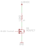
dummyload.png
 

Check in datasheets of particular device, what is maximum dissipation power and under what conditions (@25C temp).

If need more power consider adequate paralleling of devices to get more power, add big and efficient heatsink, .....
Use heatsink with smaller thermal resistance or even water cooling,... active cooling with fans,... add fan to heatisink,....

What is working time needed (few seconds or few hours) ?

TO247 about 310W per device, but manufacturer explain and give product characteristics in datasheet, check it.
 

You have not answered tpetar's question about the circuit's duty cycle, which is an important factor in estimating the amount of cooling required. Assuming that the 700W dissipation is for extended periods, there's no way a single transistor can handle it. The 714W rating is valid only if the transistor case is kept at or below 25°C.

If you provide some more information, not just the duty cycle but also a clear indication of how the transistor is to be driven, then someone can make some meaningful suggestions.
 

How did you calculate that the MOSFET is dissipating 700W power? According to the datasheet (ixdev.ixys.com/DataSheet/DS99223F(IXFH-FK120N20P).pdf), let's take 22mohm as the RDS(on). So, total circuit resistance when MOSFET is on is 5.022 ohm. Current through MOSFET = 120/(5+0.022) = ~23.9A. So, power dissipated by the MOSFET = 23.9*23.9*0.022 = 12.6W

The power will vary according to the MOSFET gate voltage, but I don't see how you come to 700W.
 

The OP has not indicated what type of driving signal he's going to use - whether it's an on-off operation or a varying one that can have any value from 0 to 12V. 700W is approximately the worst-case dissipation when the MOSFET is conducting half-way, 720W to be precise.
 

The OP has not indicated what type of driving signal he's going to use - whether it's an on-off operation or a varying one that can have any value from 0 to 12V. 700W is approximately the worst-case dissipation when the MOSFET is conducting half-way, 720W to be precise.

May I know how you calculated that?
 

Tahmid, you're thinking only in terms of switching the transistor fully on or fully off. Depending on the gate voltage, it may draw anything from 0 to the full 24A (for simplicity, let's disregard Rds(on) for the time being). Suppose the gate voltage is at a value that causes 1A of Id to flow. Then there will be a drop of 5V across the load resistor and 115V across the transistor. That causes a dissipation of 115W by the transistor and 5W by the load resistor. Transistor dissipation is maximum when Id is half of Vdd/R which is (120/5)/2 or 12A. In that state, the load resistor drops 60V and the remaining 60V is across the transistor. 60V*12A = 720W. At that point, the load resistor is dissipating exactly the same amount of power.

I've tried to make it easier to have a mental picture of how it works rather than blindly present a formula. The relevant mathematical derivations can be found in books and web resources. Of course, since the OP has remained silent after making that initial post, we still don't know whether he means to do on-off switching or a continuously variable drive.
 
  • Like
Reactions: Tahmid

    Tahmid

    Points: 2
    Helpful Answer Positive Rating
Hi All, I was been very busy for the pass few days for other project and sorry for the late reply.

The MOSFET will be used for linear application and i will apply voltage to Vgs from 0 - 12V using an op-amp with a feedback resistor connected between the
source and op-amp inverting input. The circuit acted like a basic constant current sink.

The DC bus is 120VDC and let say I will adjust a constant Id to 10A.
a) Voltage drop at the load = 10A*5 Ohm = 50V, Pd = 10A^2 * 5 ohm = 500W.
b) Voltage drop at the MOSFET: Vds = 120V - 50V = 70V.
Power dissipated at MOSFET = 70V * 10A = 700W.

Is my calculation correct for power dissipation at load and the MOSFET?
 

Yes, your calculation is correct. And, as I mentioned in the post above yours, transistor dissipation will be highest when Id is half of Vdd/R and Vds is also half of Vdd. This is a derivation of the maximum power transfer theory.

Going back to your original question of whether it's feasible to use a single transistor for the job, the answer is no. It's possible in theory but not in practice unless you use some unusual cooling method like liquid nitrogen. The 714W rating of the IXFH120N20P is at a case temperature of 25°C. Under that condition, the junction-to-case thermal resistance raises the temperature of the semiconductor chip to its maximum allowable level.

Even if you could somehow keep the case temperarue at 25°C (which is not possible with ordinary heatsinking methods), running the transistor at its max junction temp is not a good idea. Therefore, the most practicable solution is to use multiple transistors. Even then, dissipating ~700W is not a trivial matter and will require a massive heatsink or some form of active cooling like forced-air cooling.
 

Status
Not open for further replies.

Similar threads

Part and Inventory Search

Welcome to EDABoard.com

Sponsor

Back
Top