Continue to Site

Welcome to EDAboard.com

Welcome to our site! EDAboard.com is an international Electronics Discussion Forum focused on EDA software, circuits, schematics, books, theory, papers, asic, pld, 8051, DSP, Network, RF, Analog Design, PCB, Service Manuals... and a whole lot more! To participate you need to register. Registration is free. Click here to register now.

Mosfet load Switch trouble with current leakage

Status
Not open for further replies.

Tonibco

Newbie level 5
Joined
Oct 19, 2016
Messages
8
Helped
0
Reputation
0
Reaction score
0
Trophy points
1
Activity points
90
Hi There,

I hope everything is going well

I´m quite focus on adding a Mosfet as a switch, in order to block/allow the voltaje to the load.
However I´m currently getting a trouble, which is the current leakage as long as I´m blocking the switch.

I have enclosed you a shot, so as to show you the Mosfets as well as the configuration used on it.

https://obrazki.elektroda.pl/1586384200_1476951551.jpg

I hope I managed to make myself understood.

Many thanks in advance

Toni
 

Hi,

you show some text, but no values..
You show a picture but no MOSFET partname... There are two MOSFETS, but none is connected as a switch.. There are two resistors, but which of them is the load?

What answer do you expect?
What can we do for you?
Or: What exactely is your question?

Klaus
 

Hi Klaus,

First at all, Thank you for your feedback.

Alright. The purpose is to design a Mosfet as a switch, such as the following link below;

**broken link removed**

An Inertial Unit (accelerometer) will be connected into the Vout pin. This switch will be controlled by a Microcontroller, HOWEVER, the trouble is coming up when I use the uController sleep mode, since I want the Mosfet to block (cut off) the power supply with the accelerometer. So there is a current leakage flowing throughout the Mosfet, however I expect the mosfet to isolate the system.

I´m using the following Mosfet transistor (link below);

http://nl.mouser.com/ProductDetail/Infineon/IRLML2502TRPBF/?qs=%2fha2pyFaduhyxTHJ4eRB4LICl2cVVmIVQQ%2fiOh8pYBs%252b1knJNUWIhqpD8rPMRpeu

The voltage flowing through the switch will be around 3.3V.

What should I do to avoid this current leakage?

Many thanks

Toni
 

Hi,

Still you give no values.

The datasheet says that the leakage current should be below 1uV at room temperature.

I don´t know what YOU measure as leakage current. Therefore I don´t know if it is within specification or not. I can´t decide what to do, as long as you don´t give the values.

If you want an answer you need to provide all data:
* your actual circuit (not one forma any internet site)
* your values: voltages, currents..
* and all other necessary informations.

otherwise it´s impossible to help

Klaus
 

The N-ch MOSFET mentioned has a very low Vgs (min) value - only about 0,6V so it is exceptionally easy to be turned on. It appears that only about 150uA of current through upper 4.7K resistor could be enough to turn on the device, at least partially, as it has such low Rds. We do not know what P-Ch MOSFET is being used.

Full analysis requires more information
 

Thank you very much for your useful clarifications. I´m actually checking the behaviour with higher Rds Mosfet values. I will let you know the results as soon as I get it done.
 

Hi,

If you gave us the requested informations.. then the circuit would be running for more than two weeks now.


Klaus
 

Hi all,

First at all, I apoligise since I was focus in other tasks, so that I could´t reply you as soon as I expected.
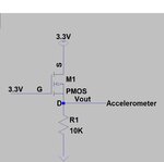
I have got some results from a Pmos transistor configuration as a switch.

As reminder, I want to clarifiy that the purpose of the circuit is to switch the Mosfet on/off, which is going to be connected to an Inertial Unit (accelerometer), and this will be connected by the Vout pin. So, we are expecting the following behaviour;

1. If the switch is 'on' mode: no matter which consumption has, so it is having a properly behaviour.
2. If the switch is in 'off' mode: Regarding my results, apparently there is no current leakage, as the
multimeter shows (I indicated a micro Ampere scale into the DMM and it shows 0 value). Since the
begining a power supply was connected to the circuit, however, I decided to replace it for a
small battery in order to check if a consumption was flowing through the circuit in 'off' mode. But I
checked it out after a while, and it is having a consumption, since the Voltage has decreased. So, I
suppose it is having a current leakage.

How to avoid it?

I am using a Pmos Transistor with the following values: Rds on= 8 ohms; Vgf= 900mV. Below is linked the datasheet:

https://nl.farnell.com/vishay/si1031r-t1-ge3/mosfet-esd-p-ch-20v-0-14a-sc-75/dp/1794820?ost=SI1031R-T1-GE3&selectedCategoryId=&categoryNameResp=Alle%2Bcategorie%25C3%25ABn&searchView=table&iscrfnonsku=false

I have also enclosed you the configuration and the values used on the draw circuit.

**broken link removed**

Thank you very much and I hope this information is useful enough.
 

The battery may have self-discharge. In any case you have
the tools to measure each branch's current and determine
which component it taking the current, or by process of
elimination, that it's the battery. This is something you
have to do, methodically, on the bench; no amount of
remote speculation will get you any closer to knowledge.
 

Check it out again, please

Mosfet as a switch.jpg

Thank you
 

Status
Not open for further replies.

Similar threads

Part and Inventory Search

Welcome to EDABoard.com

Sponsor

Back
Top