Continue to Site

Welcome to EDAboard.com

Welcome to our site! EDAboard.com is an international Electronics Discussion Forum focused on EDA software, circuits, schematics, books, theory, papers, asic, pld, 8051, DSP, Network, RF, Analog Design, PCB, Service Manuals... and a whole lot more! To participate you need to register. Registration is free. Click here to register now.

Mosfet IRF9530 Circuit Issues

Status
Not open for further replies.

Gary_SMi

Junior Member level 1
Joined
May 6, 2015
Messages
17
Helped
0
Reputation
0
Reaction score
0
Trophy points
1
Activity points
122
Hello,

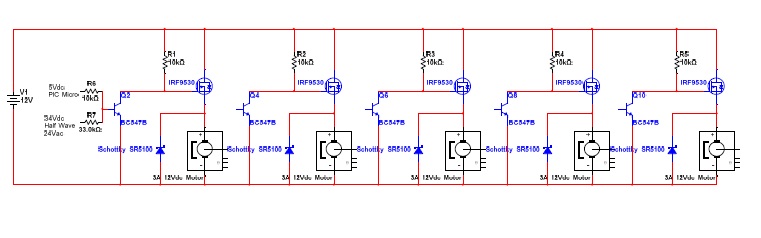
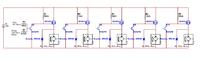
Attached describing part of a 10 channel mosfet motor drive circuit. It seems that channels are failing from time to time, either the bjt or the fets are failing either permanently ON or permanently OFF. Have recently added the schottky diodes in an attempt to rectify the problem. Can anyone spot somewhere else in the circuit that could be contributing to this problem? Thanks in advance.


Hi,

I assume high voltage spikes cause the fail. (Caused by wiring and stray inductance)

Therefore we need to see your PCB layout.
GND plane. Urgent for high speed high current switching.
And there is no capacitor at 12V line. You need at least one low ESR bulk capacitor and I recommend an additional fast capacitor at each MOSFET_source.

What switching time (turn ON , turn OFF) do you need? Maybe you could ease with slowing down swtiching edges.

Klaus
 

Hi Klaus,

Thanks for your reply. Attached pics, the power supply is 29A 12VDC Meanwell unit. Is it possible the addition of the schottkys would have solved the problem? It seems I cannot get the unit to fail on the test bench, but in the field they are failing.....


- - - Updated - - -

Additional: The motors are only switched on for 60 seconds or so at a time and now pwm or any fast switching, just either on or off

- - - Updated - - -

sp. "NOT" pwm

- - - Updated - - -

Basically replacing a relay operated system
 

Hi,

The additional schottkys are a good way to suppress some voltage peaks caused by load and wiring inductance to the load.
So maybe this solved the problem.

***
With "fast switching" I meant high dV/dt, not high frequency. With slow switchind = low dV/dt the voltage spikes are limited.

***

The wiring on the PCB is surely far away from being optimal.
The relative thin bus wires (tinned) for 12V and GND without capacitors are prone to generate voltage spikes.
Now I recognize that even the wiring from supply to this PCB may cause problems. I strongly recommend to bypass the 12V to GND with at least one 100uF low ESR electrolytic capacitor and
at least one 100nF ceramics capacitor. Best is when the 100uF is place at the middle (5 + 5) MOSFETs.

Maybe in the field the wires from supply to this PCB are long, maybe thin, and maybe the two wires (12V and GND) are not in close proximity....
Then do a Test - without the capacitors: use your scope and connect Scope_GND to PCB_GND (in the middle of the 10 MOSFETS. And connect scope_signal to PCB_12V (also in the middle of the 10 MOSFETS).

Then switch the motor ON and OFF and check for spikes.
I assume the (negative) spike when a motor is switched ON is not critical. (Although I assume the starting current of the shown motors could be close to 20A)
But I assume the spike when a motor is switched OFF may be critical. (Only one motor swtiched ON/OFF, all others are OFF)

Then add the recommended capacitors and see if there is an improvement.

Klaus
 

Thanks Klaus, will try the above. In the field wiring from supply is short but wiring to the motors can be up to 30M ... 2.5mm cabtyre. Also there are instances where more that 1 motor is energised at a time even some cases all 10 motors are energised simultaneously....
 

Hi,

On scope notice minor differences with addition of the schottkys and capacitors etc. Even the ones with the diodes and capacitors are failing in the field. To increase the dv/dt would the introduction of a capacitor on the gate do the job? Have also just got some IRF 4905 fets rated 74A going to try ..... it seems the IRF9530 are going short circuit, some are even discoloring due to heat even after a few seconds and motor runs continuously irrespective of the gate condition. The motor loads on site worst case are about 4A when running.
 

Hi,

new information:
some are even discoloring due to heat

Discolouring means high power dissipation. But transients will not cause high power.

Therefore now I assume your power supply is failing. Maybe on overcurrent condition.
Imagine at overpower condition let´s say the voltage drops (maybe for a limited time) to 6V, then the MOSFET is only partely conductive, dissipating a lot of power.

A 30A power supply with 10 loads causing 4A each may be overload. (Especially when considering high starting current. Btw: did you check starting current?)
Switch mode power supplies are more sensible against overcurrent than linear power supplies.

I recommend to use a higher rated power supply.
Or include a power supply monitoring circuit, that shuts down load when the voltage is below a certain level. About 200ms delayed switch ON.

In any case I recommend to do some overcurrent tests and check the supply voltage with a scope.
You may use 10 incandescent lamps (30...40W) as load.
They will draw a peak starting current.
Now test what happens when all 10 channels are switched ON at the same time.
Then check what happens when the channels are switched ON, each with a 100ms delay from channel to channel.

Klaus
 

Thanks Klaus, the whole thing starting to make sense now. Replaced with the 74A fet, performs way better. The power supply on startup of all 10 at the same time virtually hits 4v before recovering, when all running its ok at 12v or so. In the system all 10 are switched at the same time from time to time, so impractical to delay the startups individually from the trigger points. Would a capacitance on the gate to increase dv/dt help with the initial startup currents maybe?
 

Hi,

The power supply on startup of all 10 at the same time virtually hits 4v

Replacing the FETs won´t change much.
A gate capacitor won´t change much.

If you decide to stabilize the 12V with a capacitor, then you need about 0.1F !!!. I don´t think it makes sense.

If you can´t change the software to avoid that all channels start at the same time, then I recommend a more powerfull power supply.


Klaus
 

Makes sense Klaus. The power supplies are standard in the field for the relay operated systems so not practical either. There are 3 different ways they are used. 1.) All 10 start same time (most demanding) 2.) 5 start at a time. 3.) Software controlled where they start stop different times - (should be ok) Am running all 10 motors now off 1 channel now successfully at about 12A continuous (heat sink will be required), the input voltage drops to about 6v at start up before quickly recovering. The fet rated -74A continous at 25 deg, -260A pulsed. We have found that some older motors in the field are drawing abnormally high currents up to 6A running. These ones here running at about 1.3A or so. Do you think relays would be a more reliable solution?
 

Hi,

Again: The changed FET won´t change much. (Maybe it desn´t change anything)

And it is not important if you run 10 motors from one channel or from 10 channels (simultaneously switching)

--> The problem is powersupply behaviour combined with load current behaviour.

Relays won´t change the powersupply/load_current problem.For sure they won´t overheat. But they may awfully chatter when you switch ON all channels... Causing a lot of awful EMI.

--> again: If you can´t change the software to avoid that all channels start at the same time, then I recommend a more powerfull power supply.


Klaus
 

Status
Not open for further replies.

Similar threads

Part and Inventory Search

Welcome to EDABoard.com

Sponsor

Back
Top