Continue to Site

Welcome to EDAboard.com

Welcome to our site! EDAboard.com is an international Electronics Discussion Forum focused on EDA software, circuits, schematics, books, theory, papers, asic, pld, 8051, DSP, Network, RF, Analog Design, PCB, Service Manuals... and a whole lot more! To participate you need to register. Registration is free. Click here to register now.

MOSFET H-Bridge using IRF3205

Status
Not open for further replies.

Aazim

Newbie level 3
Joined
Jan 7, 2013
Messages
4
Helped
0
Reputation
0
Reaction score
0
Trophy points
1,281
Activity points
1,318
Assalam 0 Alaikum!

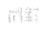
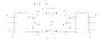
I'm designing an H-Bridge Stepper Driver circuit using MOSFET IRF3205. I'm having a lot of troubles in doing so, since last 3 weeks. Still no result..

Actually, the major problem is that, the upper side of the circuit(i.e the supply side FETs) are getting hot enough. The main Supply is 12V DC. Also, the supply at the output terminals to the motor, the FETs are giving is 7Volts approx.

Please help me..
Thanx in advance :( :(

- - - Updated - - -

I also tried with the irf4905(P-channel) in complement with irf3205(N-channel).. If you have the solution using the complementary logic, please tell that also..
I tried the circuits available on Internet also, but none of them helpful to me. :(
The problem is same with both the cases.
 

use heat sinks and then check

This is not the exact solution actually. What about the output Voltage (7 Volts, that should be 12Volts). And the Load is about 4 amperes. The IRF3205 can work upto Id=110A.
 

Are you using high-side drive for the 2 upper MOSFETs? They can't just be driven with a logic high. Since you mention you get 7V, I assume you use some sort of high-side drive. So, the problem may be in the high-side drive circuit. Please upload the schematic of your bridge and driver and then further suggestions may be provided.
 

Upload the circuit. Only Proper drive can discharge the gate capacitance of the upper mosfet.
 

Are you using high-side drive for the 2 upper MOSFETs? They can't just be driven with a logic high. Since you mention you get 7V, I assume you use some sort of high-side drive. So, the problem may be in the high-side drive circuit. Please upload the schematic of your bridge and driver and then further suggestions may be provided.

No, currently i'm not using any driving circuitry for mosfets. But i think ir2110 will be suitable. If so, plz give me the value of the Bootstrap capacitor and diode.

If you have any driver circuit of simple dc motor h-bridge driver using MOSFETs, which you think will perfectly run, plz do share it with me. Further more, it'll be helpful to me for the stepper driver.

- - - Updated - - -

Upload the circuit. Only Proper drive can discharge the gate capacitance of the upper mosfet.

The ULN2803 is used here to sink the gates of FETs.

- - - Updated - - -

Are you using high-side drive for the 2 upper MOSFETs? They can't just be driven with a logic high. Since you mention you get 7V, I assume you use some sort of high-side drive. So, the problem may be in the high-side drive circuit. Please upload the schematic of your bridge and driver and then further suggestions may be provided.

Tahmid, is this circuit perfect for the mentioned purpose...?? I found this on a website.
 

Attachments

  • Stepper.jpg
    Stepper.jpg
    118.1 KB · Views: 369
  • final circuit.png
    final circuit.png
    14.9 KB · Views: 504

for diodes use any general purpose diode will work(1N4007,5408)
for capacitor 33uf 50wv will be more than enough.

- - - Updated - - -

Go to the following link and download the application note.On page 25 cct for full bridge is given .
http://www.irf.com/technical-info/appnotes/an-978.pdf
 

IR2110 is half side gate driver ic.. I think i've to use 4 of them to operate the Stepper Motor.
But the point is, will it work with it. Actually, i have a confusion here, that considering just single h-bridge, when i apply input to Li of left and Hi of right in the initial, the bootstrap capacitor will be charged of Li side. But, will it be discharged (or will the Output disappears quickly), as i apply the invert logics on the inputs).

Suppose, the max. time for bootstrap capacitor discharging is 5 seconds approx. If i want to turn it off after 1 second, will it be normal, or will it effect my circuit...??
 

You don't need to discharge the bootstrap capacitor. Actually it is used to discharge the gate capacitance to completely switch off the mosfet. So don't worry about it
 

your output voltage is 7v because the mosfets are not properly switching, they require almost 12v pulses at the base, u must properly saturate the base mosfet
check the voltage from the ir2110, amplify the voltage if you need to and they are getting heating because the mosfet in a single leg are getting short. the deadtime should exist between switching of upper mosfet and turning off the lower transistors.

and use freewheeling diodes across the mosfets
 

if your circuit is getting heated check for max gate source voltage an current mosfet can handle
protect your gate by applyingzener voltage
 

Status
Not open for further replies.

Similar threads

Part and Inventory Search

Welcome to EDABoard.com

Sponsor

Back
Top