Continue to Site

Welcome to EDAboard.com

Welcome to our site! EDAboard.com is an international Electronics Discussion Forum focused on EDA software, circuits, schematics, books, theory, papers, asic, pld, 8051, DSP, Network, RF, Analog Design, PCB, Service Manuals... and a whole lot more! To participate you need to register. Registration is free. Click here to register now.

Mosfet getting very Hot and burn

Status
Not open for further replies.

Sharagim

Advanced Member level 4
Joined
Feb 6, 2011
Messages
112
Helped
0
Reputation
0
Reaction score
0
Trophy points
1,296
Activity points
2,058
Hi,
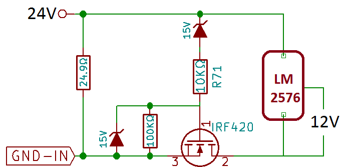
In this schematic when VCC feed with less than 1AMP mosfet getting HOT in some seconds and will burn if wont stop VCC(even if I feed with 300mA it will get HOT and blow), At this stage I see voltage drop so the Gate voltage will be something like 3~4V and seems the Mosfet is not ON completely.
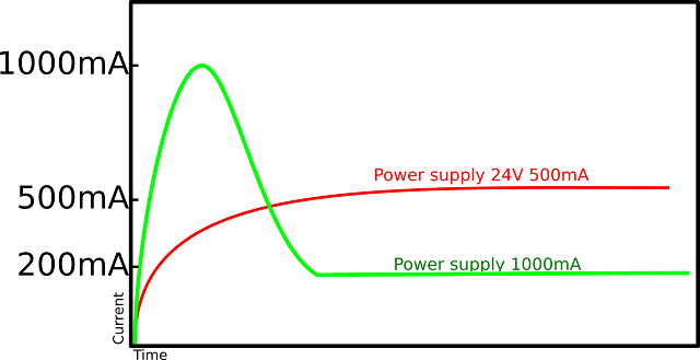
If I feed with high current then I see it will take full load for a few milliseconds and then will go normal, continuously the current will be 200mA.
I think the problem is that the system couldn't bring the mosfet ON completely and as it is partially ON this problem occur!


Hi,

An LM2576 has 5 pins. It is impossible to connect two pins only.
Even if it is just a symbol for a LM2576_circuit...it needs at least three terminals: input, GND, output.
And you need to specify the output voltage.

Klaus
 

What are the voltages at nodes ?? VCC ??
 

Sorry I forget to mention:
Output voltage is 12V(The LM2576 version is D2Pak).
Input Voltage is 24V.
Also I am using this circuit for POE.


The question is unclear. "VCC feed with less than 1AMP" suggests a current limited source. "Input Voltage is 24V" means no current limit.

In the former case, it's well possible that the transistor is overloaded. I wonder what's the purpose of the transistor circuit. If you want to block the power supply below a specific input voltage, you better control the LM2576 on/off input.
 

Sorry I forget to mention:
Output voltage is 12V(The LM2576 version is D2Pak).
Input Voltage is 24V.
Also I am using this circuit for POE.


Is the actual circuit like that or ? Because the application circuit of LM2576 is not like that and if you haven't applied the necessary components, your circuit may oscillate and it would destroys all..
What is the purpose of MOS ?? In order to make the circuit ON when supply voltage is if only and only over a certain threshold ?? You should do this more smart..
 

Hi,
BigBoss: Is the actual circuit like that or ? Because the application circuit of LM2576 is not like that and if you haven't applied the necessary components, your circuit may oscillate and it would destroys all.....
I use LM2576 as a symbol here, sure I used full circuits components like the image below.

This is a circuit for POE (Power Over Ethernet) and IEEE 802.3af.
Power source equipment will detect 25K(24.9k) resistor by applying low voltage (2.8V~10V), During this 25K signature detection POE device shouldn't take current. After Power source detect the 25K resistor then it will apply main Voltage which will be 24V or 48V.
FvM: The question is unclear. "VCC feed with less than 1AMP" suggests a current limited source. "Input Voltage is 24V" means no current limit...
For example when the load is 200mA and the power supply is 24V/500mA this problem exist but with same load when the power supply is 24V/1000mA the problem gone.
 

For example when the load is 200mA and the power supply is 24V/500mA this problem exist but with same load when the power supply is 24V/1000mA the problem gone.
I see, that's expectable by design. Get rid of the misbehaving Z-diode and MOSFET circuit and control LM2576 on/off pin by voltage threshold detector.
 

Do you have a Heat Sink on the MOSFET?
Without a Heat Sink, the Actual Current Rating on the MOSFET is MUCH LOWER than the data sheets specification.
 

The mosfet rating is 500V,2.4A,42W so for sure with 200mA load it wont be an issue.
At the problem point I see the Gate voltage is about 3.5V so I think the mosfet is not turn on completely and by measuring the mosfet output it confirm which it is not on.
 

The mosfet rating is 500V,2.4A,42W so for sure with 200mA load it wont be an issue.
At the problem point I see the Gate voltage is about 3.5V so I think the mosfet is not turn on completely and by measuring the mosfet output it confirm which it is not on.

Full On requires 10 Volts on the Gate and even than its Drain to Source resistance is 3 Ohms.
With only 3.5 Volts, I would imagine it would be Quite High in Resistance, so 200 mA would cause Heating, ESPECIALLY Without a Heat Sink.

(A Lower Voltage MOSFET would have a LOWER On Resistance and more Suitable for your purpose.)
 

Hi,

The mosfet rating is 500V,2.4A,42W so for sure with 200mA load it wont be an issue.
You just read the three values. But you need to read the conditions to the specifications, too.

The datasheet surely doesn't specify 42W without heatsink.

Klaus
 

As already confirmed by Sharagim, the posted circuit has the unwanted side-effect to stay in a linear MOSFET operation point under certain source and load conditions.

That's not a problem of specific MOSFET parameters but of not well considered circuit operation. There are better ways to achieve the specified circuit purpose.
 
Hi,
As already confirmed by Sharagim, the posted circuit has the unwanted side-effect to stay in a linear MOSFET operation point under certain source and load conditions....
You are completely right and this is my issue which MOSFET is not working properly, could you please give me some ideas what are those considerations and what is better way which you mention before.
 

I reviewed PoE specifications and found that the signature capacitance limit of 0.15 uF doesn't allow to connect a switching regulator like LM2576 directly. In so far my idea of implementing a simple undervoltage lockout for the switcher doesn't work, at least not with this regulator.

A disconnect switch in front of the regulator seems necessary. Instead of controlling the gate voltage with a Z-diode, you should use a threshold detector with hysteresis, switching the MOSFET either fully on or off. In addition the switching regulator should use reasonable soft-start so that the PoE supply current limit isn't triggered during start-up.
 
Thanks for replies.
FvM: . Instead of controlling the gate voltage with a Z-diode, you should use a threshold detector with hysteresis,
Could you please let me know if you believe this threshold detector should be build with OPAMP !?
 

Status
Not open for further replies.

Similar threads

Part and Inventory Search

Welcome to EDABoard.com

Sponsor

Back
Top