Continue to Site

Welcome to EDAboard.com

Welcome to our site! EDAboard.com is an international Electronics Discussion Forum focused on EDA software, circuits, schematics, books, theory, papers, asic, pld, 8051, DSP, Network, RF, Analog Design, PCB, Service Manuals... and a whole lot more! To participate you need to register. Registration is free. Click here to register now.

MOSFET Current Limiter

Status
Not open for further replies.

rbenditt

Newbie level 4
Joined
Dec 30, 2008
Messages
7
Helped
0
Reputation
0
Reaction score
0
Trophy points
1,281
Activity points
1,371
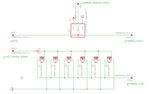
Hello everyone. I've got a current limiter circuit that I'm working on here that "almost works". I've attached a schematic below.

attachment.php


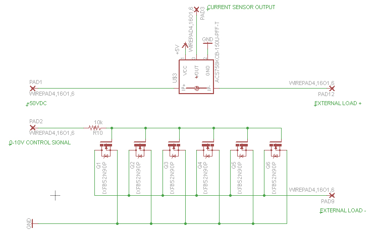
The circuit sends 50 VDC to an external load whose resistance varies. The incoming current first goes through a current sensor whose output signal goes to a microcontroller (not shown). The microcontroller evaluates the current measurement and adjusts an analog output to between 0 and 10 volts. This control voltage is connected to the bases of six MOSFET transistors to throttle the current that goes through them.

What is happening in my test circuit is that the current is indeed being limited. When I make the microcontroller send different control voltages, the output current changes accordingly. The problem is that I keep frying the MOSFETs. I'm putting 30 amps through the external load and the MOSFETS should be good for 52A / 1250W each. Since I've got six of them in parallel, I don't get why I'm frying them. I'm not an electrical engineer so I may be approaching this in a completely wrong way. Any suggestions?

Thanks,

Ron
 

Attachments

  • CurrentLimiter.jpg
    CurrentLimiter.jpg
    123.1 KB · Views: 1,125

The mosfet (and transistors too) can work with very high current but when they are actually to a state that they have very low resistance (Rds-on for mosfet, Vce for transistor),
when you use the mosfets to limit the output current then the power consumption on the mosfet is the output current multiplied with the drain-source voltage and this creates too much heat.
The mosfet should be either on or off, anything between with such high current will create overheat problems.

Alex

---------- Post added at 19:08 ---------- Previous post was at 19:05 ----------

and 52A / 1250W is where you are actually wrong, can you imagine that king of heat on a small device, how is it supposed to manage that.
If you read the datasheet there is something called SOA (safe operating area) , it shows the max current for a given voltage drop across the mosfet

Alex
 

Yes, I think you're right about that. The heat dissipation is a bit unrealistic. I don't see a chart like you are talking about in the data sheet, but I'm probably interpreting things incorrectly. I see a few "output characteristcs" graphs that show how much current (Id) flows given a Vds and Vgs voltage. I do see a chart that shows maximum drain current (Id) for a given case temperature. For 30 amps, it looks like I can get away with a case temperature of 112 degrees C. But... since I've got six FETs sharing the load (more or less equally), then I'm really only pushing about 5 amps through each one and should be good to a case temperature up to around 150 degrees C. That's pretty hot! About the point where the plastic is going to melt off!

Anyway, I have a feeling that I'm approaching this current limiting business in the wrong way. In my application, the output load is an electric motor that, in normal use, is fine. But occasionally the output shaft is loaded up to the point of causing the motor to stall. When this happens, the motor draws huge amounts of current and fries itself. This is why I'd like to put some kind of current limiter circuit ahead of the motor.

My first thought on the matter was to just use a simple resistor in series with the input and be done with it. But it would have to be rated for about 6KW or so! Plus, it would be a big-time power drainer.

Another thought that I've had was to use a mechanical slip-clutch to prevent the stall condition. The problem is... there isn't any room to physically mount one.

I've also ruled out just using a simple fuse. In this application, the circuit needs to be able to recover from over-current conditions quickly and on its own to get the motor back and running ASAP. Even those self-resetting fuses would take too long to allow the circuit to come back to life.

So that's how I came to use MOSFETs... it seemed like I could throttle the current to the load as needed. But they get hot and burn themselves up... at least in the way that I'm implementing things.

Any ideas? I feel kind of stuck at the moment.

Ron
 

The SOA graph is like this (graph is from APEC AP4800 Nmosfet)

mosfet_SOA.gif

The normal way to limit current is by using PWM to control the ON/OFF ratio but I don't think that you need something like that.

I think you can use the control device to cut the power to the motor (mosfets turned off) when the current is above the limit and then try after a small delay to provide power again (full on), if it is above the limit then cut the power again and do this loop (with a small delay each time ) until the current is within range and then keep the power on.

The mosfets should be either on/off or you will have problems,
a mosfets need to be turned on/off quickly and to do that you need a proper gate drive to be able to provide high current.
Your gate resistor doesn't help on that but even if you remove it the driving stage will not be able to provide the high current needed.

Think of the mosfet gate as a capacitor, you have to charge it to turn on the mosfet and discharge it to turn off the mosfet.
The more current you are able to source/sink the faster it will turn on/off and it passes very fast from that middle on/off state to avoid the heat because of high current and voltage drop.
When the mosfet is off you have no current an high voltage drop , when it is on you have high current and low voltage drop, you are ok in both of these states.

A proper mosfet driver looks like this

Nmosfet_driver.jpg

but there are many mosfet driver IC that you can use if the switching rate is high,
if the rate is low you can get away with a low current driver, even a simple resistor.

Alex
 

The 10k resistor limits the gate current to about 1mA @10v, it will take about 300u sec x 6(mosfets) =1.8ms to turn on or off the mosfets,
any on or off duration and also the delay between tries should be higher than that.

If your mcu is able to provide 10mA then you can limit that time to 1/10 (0.18ms) with a 1k gate resistor.

Alex
 

Ah, my data sheet for IXYS's IXFB52N90P FET doesn't have an SOA graph like that. I wish it did!

I get what you mean about turning the motor off when the limit is hit and then trying later after a delay. I don't think that I can do this though because it's not just a motor... there is a motor controller that gets all the power and the motor is attached directly to the controller. If I were to shut the motor controller down and then restart it, there's a startup routine that it goes through. I'm not sure how this would work out. I'll have to think on that one.

I did a SPICE simulation and I can see what you mean... at intermediate Vgs values, the watts that are dissipated through each FET are quite high. Really high, in fact!

attachment.php


In the graphs, as time goes on (left to right), the gate voltage is varied. The various plots represent output current to the load and the power dissipated by one FET, all at various output load resistances.

I forgot to include the resistor and capacitor that are connected to the gates in my original schematic upload. This is meant to drain off the gate charge when the control voltage is changed. Without this, the capacitance of the FETs would keep the gate open nearly forever even with a zero control voltage.

Anyway, it's pretty clear that the FETs are dissipating LOTS of power in my implementation, so that explains why they're burning out. Just not sure where to go from here at the moment. I'll give some thought to the implications of power-cycling the motor controller. That may be a possibility.

Ron
 

Attachments

  • CurrentLimiterSimulation.jpg
    CurrentLimiterSimulation.jpg
    722.5 KB · Views: 585

Yes, I should be able to get away with a 1K gate resistor.
 

How does this (motor)controller behave when you reduce the voltage to it , because this is what you are doing to limit the current.
Does it have any kind of protection to turn off the motor below a voltage threshold?

The PWM would be a possibility but this controller complicates things, I thought you could use a 50% duty cycle when there is a current limit on
or go to 100% when everything is OK (you will need a mosfet driver of course) but I don't know if this will work with the motor controller in the middle.
I don't know what will happen if you apply high rate pulses in the controller input (for example 5KHz)

Alex
 

I'm not sure how the motor controller reacts to voltage fluctuations. I do know that it works with a variety of input voltages and thankfully, I'm running it near the high side in normal use. So presumably I have at least some room to ramp down before it does bad things. Oh... wait.. yes, it does have a low-limit shutdown. This is intended to protect the batteries that are running it. If the batteries drain below a certain level, they can't be recharged again. This is why the controller limits things. This kind of complicates things. Normally, current limiting is not needed and the motor should run at or near full input voltage (50V). If bad things start to happen (high current requirement is detected), then I'd like to start throttling things back. In this condition, the input voltage to the motor would then be reduced, probably below the controller's cut-off threshold. I think, but I need to verify, that once the voltage comes back up, the controller turns things back on again.

PWM to the motor controller probably would be a bad idea. The controller has some digital aspects to it (as opposed to just an analog type of thing), so PWM to its input would probably mess things up.

Ron
 

Are the batteries for backup only, are you able to use any voltage source lower than the 50v,
if for example you were able to get a lower voltage from say middle point of the batteries then you could limit the voltage to the motor using a switch between 25v or 50v.
Do you have any source from where you can get a voltage lower than the 50v?

Alex
 

The batteries are the main power source, not just for back-up. I have to be really careful about tapping off different voltages from the cells on the battery pack, otherwise the battery cells won't be balanced and this will lead to recharging problems. I do have some other devices running at different voltages, like 5V and 12v, but to do this, I've attached voltage regulators to the 50V battery output. Also, running the motor at a lower voltage than 50V will greatly limit the motor's power output.

Ron
 

Also, running the motor at a lower voltage than 50V will greatly limit the motor's power output.

That is exactly what we want, to limit the current when there is problem.

So PWM is not a solution , maybe with an output filter but the current is high and I don't know if it would work,
you don't have any source from where to get a lower voltage
and using some kind of device to add resistance will generate too much heat.

I can't think of another way.

Alex
 

I've been looking at that SPICE simulation output again. You know what? In normal use, with the gates fully open, the power dissipation of each FET is only 6 watts. That doesn't seem that bad. When bad things happen at the motor and the FETs need to do limiting, they start to dissipate as much as 200 watts each. In my experimenting with the real circuit, this is likely what happened. During my last FET burnout, I was throttling a normal 30 amp output back to only 9 amps by changing the control voltage. It worked for about a minute (I could tell that the motor speed got slower when the control voltage was changed) then FETs started smoking!

Ron
 

Status
Not open for further replies.

Similar threads

Part and Inventory Search

Welcome to EDABoard.com

Sponsor

Back
Top