lzhong1
Newbie level 2

- Joined
- Dec 10, 2013
- Messages
- 2
- Helped
- 0
- Reputation
- 0
- Reaction score
- 0
- Trophy points
- 1
- Activity points
- 18
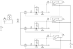
I have designed a NMOS controlled high power LED circuit as attached.
Purpose of this circuit:
1. when one of the LEDs degraded (Vf decrease), the current flow through it will be decreased as well.
2. the rest LEDs which working in normal condition will get more current since the total current is supplied by a constant current driver.
3. LM358 will amplifier the voltage across LED then supply to the Gate of corresponding MOSFET.
4. MOSFET works like a voltage controlled resistor.
But the problem is:
1. It's hard for me to set the corresponding resistance value to each resistors
2. When I set the R1:R2 of LM358 as 1.5:1, the result is correct, however, if adjust to 2:1, the result is wrong.
Hope anyone can help me to find out the circuit problem or how to set the values of the resistors!
Thanks in advance!!!

