Continue to Site

Welcome to EDAboard.com

Welcome to our site! EDAboard.com is an international Electronics Discussion Forum focused on EDA software, circuits, schematics, books, theory, papers, asic, pld, 8051, DSP, Network, RF, Analog Design, PCB, Service Manuals... and a whole lot more! To participate you need to register. Registration is free. Click here to register now.

[SOLVED] Moscap curve: Cap vs. Vgs

Status
Not open for further replies.

fuxinmingming

Member level 1
Joined
Nov 2, 2007
Messages
36
Helped
0
Reputation
0
Reaction score
0
Trophy points
1,286
Location
China
Activity points
1,538
Hi guys,

i simulated the current through moscap to get cap's value. Here is the curve:
67_1295850004.jpg


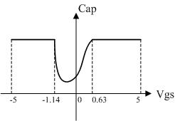
Can someone pls explain?

1. Why the curve is not symmetrical with axis y(Vgs left=-1.14V, Vgs right=0.63V, why Vgs left \neq Vgs right) ?

2. I know the maximum value is W\cdot L\cdot Cox, but what's the minimum value of the cap? Can i calculate it?

Regards

Ming

---------- Post added at 07:28 ---------- Previous post was at 07:26 ----------

2. I know the maximum value is W\cdot L\cdot Cox, but what's the minimum value of the cap? Can i calculate it?

sorry for the mistake, it's WLCox.
 

1. It is caused by different mode for MOS capacitor. Accumulating mode or inverse mode.
 

Accumulating mode or inverse mode.

Hi leo,

What's accumulating mode and inverse mode? Can you explain it in detail ?

but what's the minimum value of the cap? Can i calculate it?

Is it overlap capacitance for the minimum value? (say WLCov)

Regards,

Ming
 

See the foll. PDF: MOSCAP.pdf

Hi erikl,

I see the pdf. Now, I understand the accumulating and inverse mode. However, one of pdf 's graph confused me.

My question is:
Why the poly/n-well capacitor satisfactorily operates only if the gate voltage is positive enough ?

I think the curve should be like this:
33_1295923299.jpg


Regards,

Ming
 

Hi Ming,
In the above curve, the vertical VTH marking should be more to the right, and you are right saying the (LF) inversion rise should be less steep than the accumulation rise.

My question is:
Why the poly/n-well capacitor satisfactorily operates only if the gate voltage is positive enough ?
You need full accumulation/inversion (corresponding to strong inversion of a MOSFET), i.e. Vth + Voverdrive in order to profit from the largest cap/area ratio.

For LF applications, however, the MOSCAP also works with (enough) negative gate voltage. See the nmos- and pmos-gate-cap behavior (simulated and measured curves) below.
nmos-gate-cap.png pmos-gate-cap.png
BTW: don't feel irritated by the seemingly inconsistently used terms accumulation & inversion, this just depends on the relative charge signs of the gate and the substrate below.
 
Hi erikl,

Thanks for your explanation. It helps me a lot.

Regards

Ming
 

Status
Not open for further replies.

Part and Inventory Search

Welcome to EDABoard.com

Sponsor

Back
Top