anhnha
Full Member level 6
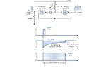
Hi all,
I feel very confused with the oppsitition between the explaination in text and the diagram which is illustrated.
The explaination in text:
"When a positive trigger pulse is applied to the input at time t0, the output of the first NOR gate U1 goes LOW taking with it the left hand plate of capacitor CT thereby discharging the capacitor. As both plates of the capacitor are now at logic level "0", so too is the input to the second NOR gate, U2 resulting in an output equal to logic level "1". This then represents the circuits second state, the "Unstable State" with an output voltage equal to +Vcc"
But in the diagram, the capacitor is charging.
As for me, I think that positive trigger pulse is applied to the input at time t0 the capacitor is charged because the output of NOR gate U1 is low and the right plate of cap is High.
But I dont see how cap is discharged because when output of NOR gate U1 is High and the right plate of cap is High, hence there is no voltage dropping in capacitor and cap is not discharged.
Am I right?
Thanks so much.