rfkevin
Newbie level 4
I got a problem when I use momentum to simulate inductor/transformer. My inductor spiral is at M6 and is connected to underpass at M5 through via5 in D5. So, my substrate setup is like this
------Strip m6 (thickness expansion down)
D5 [VIA] via5
------Strip m5
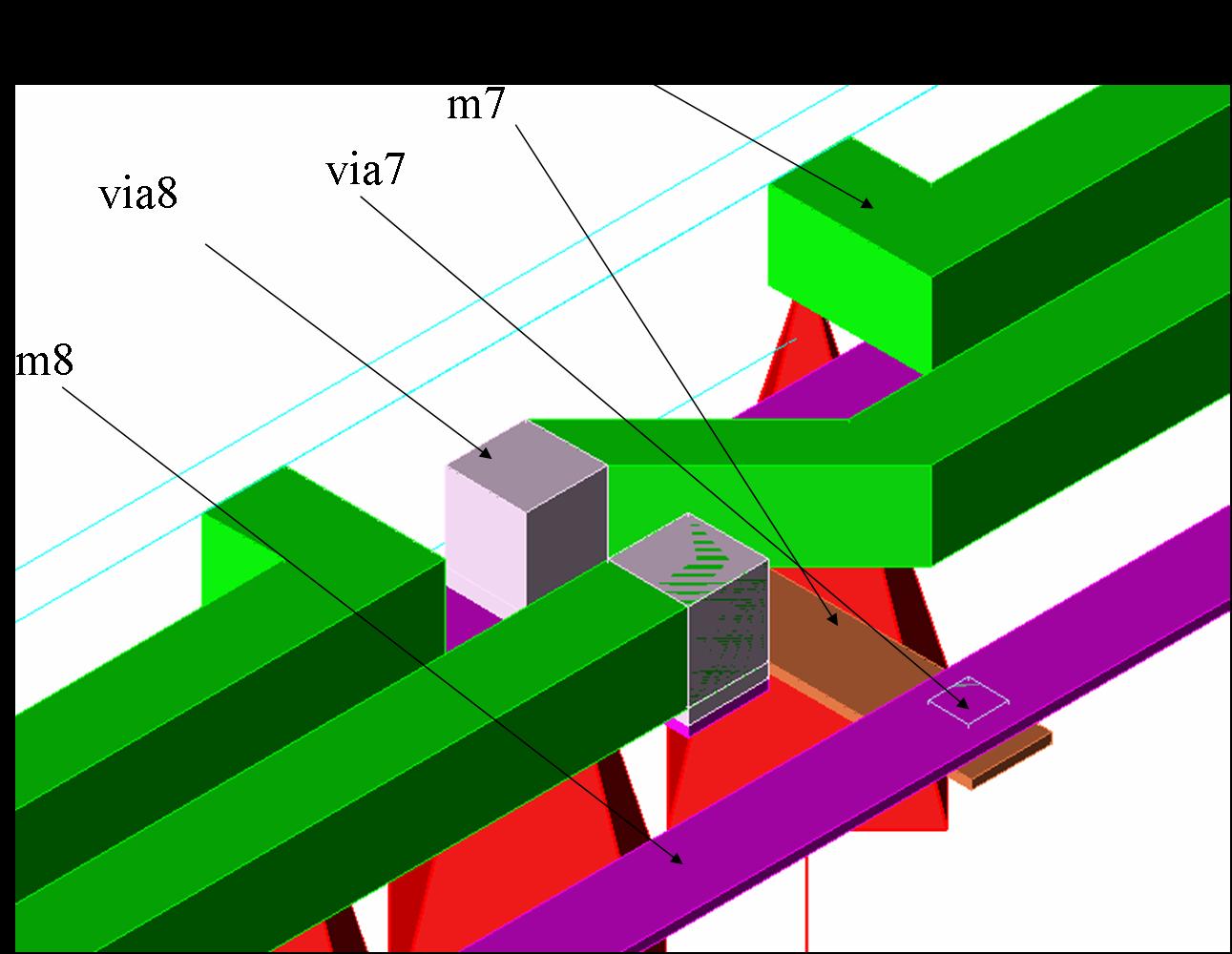
When I check the structure in 3D view, I found via5 starts from top surface of m5 to the top surface of m6. However, via5 is assumed inserted between top surface of m5 and the bottom surface of m6. I guess it is because "thickness expansion down" option of m6, which expand the dielectric layer with the same thickness of m6 and with the same permittivity of D5.
Does anyone have experience to solve this problem? Thanks.
------Strip m6 (thickness expansion down)
D5 [VIA] via5
------Strip m5
When I check the structure in 3D view, I found via5 starts from top surface of m5 to the top surface of m6. However, via5 is assumed inserted between top surface of m5 and the bottom surface of m6. I guess it is because "thickness expansion down" option of m6, which expand the dielectric layer with the same thickness of m6 and with the same permittivity of D5.
Does anyone have experience to solve this problem? Thanks.