Degrees
Newbie level 1
Hey guys, I'm quite new to electronics. I'm currently studying to be an avionics (aviation electronics) tech but so far have only done electrical fundamentals and some basic electronics involving transistors, servomechanisms, IC's.
The problem I'm having is, I bought some cheap dodgy rudder pedals off ebay to use on my flight simulator. Rudder pedals in an aeroplane are supposed to be linked together and oppose each other. The pedals I have are more like car pedals in the way that they have two completely different axis.
I want to know if it's possible to change the wiring so that the two pedals are on the same axis. My understanding is that maybe right would be +10, left would be -10 and a null 0 when no pedals are pressed (they're spring loaded).
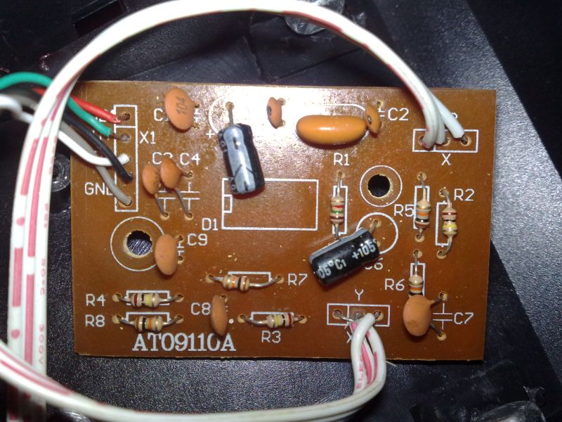
I've attached a pic of the PCB, the white wires are linked to potentiometers, one each pedal. There's also an IC on the back for the USB interface I would guess.

The problem I'm having is, I bought some cheap dodgy rudder pedals off ebay to use on my flight simulator. Rudder pedals in an aeroplane are supposed to be linked together and oppose each other. The pedals I have are more like car pedals in the way that they have two completely different axis.
I want to know if it's possible to change the wiring so that the two pedals are on the same axis. My understanding is that maybe right would be +10, left would be -10 and a null 0 when no pedals are pressed (they're spring loaded).
I've attached a pic of the PCB, the white wires are linked to potentiometers, one each pedal. There's also an IC on the back for the USB interface I would guess.