tiff_lee
Newbie level 3

- Joined
- Dec 14, 2013
- Messages
- 3
- Helped
- 0
- Reputation
- 0
- Reaction score
- 0
- Trophy points
- 1
- Activity points
- 47
Hello all new member seeking some advice/help although I don't expect to be spoon fed just nudged in the right direction as i'm looking to learn 
Right the problem, my home cinema audio processor (Audiolab 8200AP) has a trigger system to turn on additional amplifiers/gadgets whenever it's turned on (via 3.5mm mono/stereo jack cable), the problem with this trigger is that instead of a 12V DC output which seems to be standard amongst most AV equipment it uses a open/close circuit system whereby it shorts the 'pin' (would be left audio on a stereo jack) and the sleeve/ground. To make matters more confusing audiolab produce their own range of amplifiers some of which use a 12V trigger but only 1 which uses this open/close system so I have 3 output triggers and nothing to use them, cheers Audiolab.
The trigger board itself is a standalone PCB as can be seen here


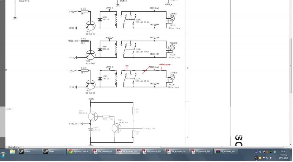
As you can see there is 3 x 3.5mm sockets, when the relays energise 2 pins of the socket are shorted hence the open/close loop. Now my idea was to break the circuit between the socket and the relay (supply to sleeve of mono jack) earth the socket side so the sleeve is always earth and then route a 12V supply to the other side of the circuit so when the relay energises the pin of the socket/jack becomes live.
Here is the service manual diagram and my proposed mod (i'm not sure if con1/3 is the tip/sleeve but will be easy to find out with a meter the image is just to illustrate my idea).

Is it even possible to break the tracks/trace on a laminated PCB? or will I need to physically disconnect the socket/relay from the board and mod it? no great shakes just looking at options.
The next step would be deriving a 12VDC supply within the unit to supply this circuit but i'll leave that query on the backburner for now and try to solve this problem first to avoid confusion.
Right the problem, my home cinema audio processor (Audiolab 8200AP) has a trigger system to turn on additional amplifiers/gadgets whenever it's turned on (via 3.5mm mono/stereo jack cable), the problem with this trigger is that instead of a 12V DC output which seems to be standard amongst most AV equipment it uses a open/close circuit system whereby it shorts the 'pin' (would be left audio on a stereo jack) and the sleeve/ground. To make matters more confusing audiolab produce their own range of amplifiers some of which use a 12V trigger but only 1 which uses this open/close system so I have 3 output triggers and nothing to use them, cheers Audiolab.
The trigger board itself is a standalone PCB as can be seen here


As you can see there is 3 x 3.5mm sockets, when the relays energise 2 pins of the socket are shorted hence the open/close loop. Now my idea was to break the circuit between the socket and the relay (supply to sleeve of mono jack) earth the socket side so the sleeve is always earth and then route a 12V supply to the other side of the circuit so when the relay energises the pin of the socket/jack becomes live.
Here is the service manual diagram and my proposed mod (i'm not sure if con1/3 is the tip/sleeve but will be easy to find out with a meter the image is just to illustrate my idea).

Is it even possible to break the tracks/trace on a laminated PCB? or will I need to physically disconnect the socket/relay from the board and mod it? no great shakes just looking at options.
The next step would be deriving a 12VDC supply within the unit to supply this circuit but i'll leave that query on the backburner for now and try to solve this problem first to avoid confusion.

