Kick
Full Member level 6
- Joined
- Sep 27, 2010
- Messages
- 344
- Helped
- 16
- Reputation
- 32
- Reaction score
- 15
- Trophy points
- 1,298
- Location
- India,Bangalore
- Activity points
- 3,170
Hiii all,
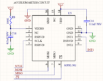
I am in trouble. Actually our PCB has fabricated and one of the component in PCB consuming more current (it will lead to early death of 3V battery,we are expecting at least 3yr.). At last we found the component is resistor R8 (see the circuit). So I need to get rid of this resistor,but we can't fabricate board again. I have 2 solutions in my mind,
1. Replace that resistor from PCB and short pads of R8.
2. Use 0 ohm resistor (not sure about this).
Can anyone suggest which one is the best way? or is there any other idea?