jumbodas
Newbie
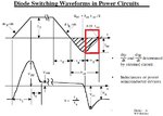
Basic spice diode model uses diffusion capacitor to account for reverse recovery. However a capacitor can't have stored charge at zero potential. As a result spice model snaps to zero current as soon as peak negative current is reached as this coincides with diode reaching to zero potential from forward bias.
However we know in real diode reverse current decays slowly after peak to remove remaining charge, while diode had zero cross over and reaches to applied negative bias possibly with some overshoot based on circuit impedance.
Can someone explain what is the physical significance, behavioral model and mathematical derivation for remaining charge?