vinodstanur
Advanced Member level 3
- Joined
- Oct 31, 2009
- Messages
- 751
- Helped
- 114
- Reputation
- 234
- Reaction score
- 114
- Trophy points
- 1,333
- Location
- Kerala (INDIA)
- Activity points
- 7,054
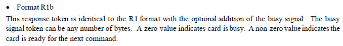
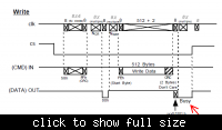
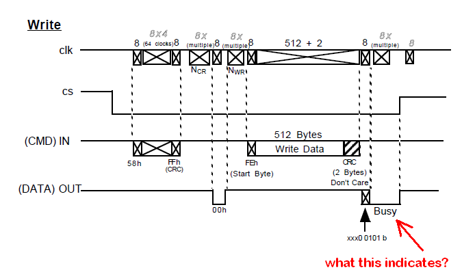
MMC multiple block write problem. (What is "BUSY" in the diagram i provided?)
Reading part is okay...I could read multiple blocks untill the card reads its entire memory.(64MB). Now,
I want to write blocks to MMC continously.(using CMD24) But after few blocks write, it is getting inside "error0" or "error1" loops.
I had written the write block code by looking on the above figure.(snap shoot from a hitachi MMC spec.
Now i doubt some error in my code . I could'nt understand that "busy" in figure . What to do for that in program?
It says that,

Reading part is okay...I could read multiple blocks untill the card reads its entire memory.(64MB). Now,
I want to write blocks to MMC continously.(using CMD24) But after few blocks write, it is getting inside "error0" or "error1" loops.
I had written the write block code by looking on the above figure.(snap shoot from a hitachi MMC spec.
Code:
void write()//
	{
	count=0;
	/*write 512 blocks*/
	command(25,arg,0xff);
	while(readdata!=0){spi_read();printf("error0");}
g:	spi_write(0xff);
	spi_write(0xff);
	spi_write(0xfe);
	for(int g=0;g<512;g++)
		{
		ADGO=1;
		while(ADGO);
		spi_write(ADRESL);
		PORTD=ADRESL;//to see adc reading in 8 leds in PORTD
		}
	spi_write(0xff);
	spi_write(0xff);
	spi_read();
	while((readdata&0b00011111)!=0x05){spi_read();printf("error1");}
	while(readdata==0){spi_read();}
	goto g;
}It says that,