Continue to Site

Welcome to EDAboard.com

Welcome to our site! EDAboard.com is an international Electronics Discussion Forum focused on EDA software, circuits, schematics, books, theory, papers, asic, pld, 8051, DSP, Network, RF, Analog Design, PCB, Service Manuals... and a whole lot more! To participate you need to register. Registration is free. Click here to register now.

mixed-signal PCB design questions

Status
Not open for further replies.
You circuit is all analogue - there is no digital. The point where you would put a split is usually under the ADC with the digital ground on one side and the analogue on the other. However, if you are interfacing to a PLC, all you will have is an analogue ground into the PLC so I don't think you have any choices. I tend to put a small inductor in series with the supplies when designing for sensitive systems (a few uH). You could use a ferrite bead, which you can get in chip form. The one place you won't put one is ground though.

Keith.
 

Hello Keith,

I understand that the majority of the circuit is analog. But I was under the assumption that the signals coming from the PLC (namely digital I/O) would be digital. Thus the need for the split ground. I am still climbing a step learning curve though.

So if I understand you correctly I just need some ferrite beads on the signals coming from the Digital I/O? There is also a ground pin associated with each of the PLC Digital Outputs on a larger system I am working on, would these not be better tied to a DGND? Or just having ferrite beads at each of the interfaces to my board is what I need?
 

The problem is that I cannot see where your circuit connects to the PLC and what other circuitry is being used on the PLC or what PLC connections are available. Presumably it has an ADC in it? Does it have separate analogue grounds? Maybe if you can link to the PLC technical documentation or at least the I/O module then that would help. If it has a differential input then that would help - you can then loosely connect the ground and connect the other end of the differential input to the analogue ground.

You wouldn't normally put beads on the digital I/O lines, but you often use them to clean up the power supplies a bit.

Keith.
 

Here is the Power supply information for the PLC used with the current design:

3. Power Supply
The T100MD888+ PLC requires a single regulated, 12 to 24V (+/- 5% ripple) DC
power supply for both the CPU and the I/Os. It is recommended that whenever
possible, use a higher power supply voltage since the voltage difference between
ON and OFF state is wider for operation at higher voltage. To use the T100MD888+
at 12VDC you should place a jumper block on the two-pin header marked “J1-12V”
near the power supply terminals. You must remember to remove the jumper when
operating the PLC above 18V, otherwise the voltage regulator may overheat.
Please use only industrial grade linear or switching regulated power supply from
established manufacturers. Using a poorly-made switching power supply can give
rise to a lot of problems if the noisy high frequency switching signals are not filtered
properly. Note: If your application demands very stable analog I/Os you should
choose a linear power supply instead of a switching power source for the CPU.
[/b]

The PLC itself can supply a fixed 5V ref from the analog I/O connector. But I need the +12V for the amplification circuits. Both the Analog and Digital systems of the PLC are powered by a single power supply.

Here is a link to the PLC info https://www.tri-plc.com/t100md888.htm

Thanks for the help
 

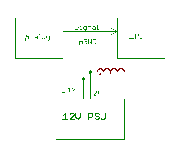
OK, that is clearer (I think). The analogue connections to the 15 way D type also have an analogue ground which is what you should use for your analogue outputs from your circuit and no ferrite beads. You then have the problem of how to run it all off one power supply because that will connect the grounds between the digital and analogue sections. So, that is where you should consider a ferrite bead

77_1281548494.gif


There other options such as also putting one (or more) in the +12V to either the analogue and/or CPU and maybe putting one in the 0V to the analogue. All of these can be done off the PCB, so it shouldn't stop you getting the PCB made. You could add places to put a bead in both the +12V input and 0V inputs on the analogue PCB - you don't have to use them if you find you don't need them.

Keith.
 

Thanks for the input

I am on may way, I think?

Again thanks for the quick help. :)

Added after 1 hours 27 minutes:

Ok I have looked into using the 0V ref from the analog D connector on the PLC. It seems as though that 5 - 0V ref is on a separate plane from the +12V input. They are making the analog 5V ref with ref chip, I am not sure why they would do it that way, but anyway it makes this method non usable.

I am planning to connect the two planes with a 0ohm resistor if the bead is truly not advisable. I have read that both methods can be used for isolating the grounds.

Another option I am looking at is placing a second L7812 in the circuit and creating a separate analog power plane (another option I have read of).
 

I realized late yesterday that the pdf I attached was not the full schematic. Sorry about that I hope this helps a little.
 

Hi ryanb,
You can find a lot of suggestions for AGND & DGNDs, but only some are relevant for you.
Your system is not a hig-speed one, these will be (maybe) not a big issue with GND separations....
Anyway, they makes a ref for +2,5V because its noise is extreme low_at 2-5uVrms!_ for that is intelligent to separate the GNDs & use shilded wires for Uref too_if you can! Be care pls, they can deliver only 15mAmps...
Otherwise is a lowpass filter for Uref befor connecting to the ADCs(& a smalll 2.2..10uF Ceramics) is a good praxis too! :)
I would connect (as Keith mentioned too) the both GNDs/planes at the ADCs with a Ferrite Bead (or even only a "0-Ohm" resistor), but GND-separations in industrial environments are (in my opinion) very useful/welcome!
But even so important is the separation of the Supply voltages too...A ferrite bead is nowaday nothing by place problems, has a footprint of only 1206! :)
FOR LOW NOISE SUPPLIES FORGET pls THE OLD 7812 (& family!!), they are todays LDOs the solution, then (practically) all have up to ten times lower noises at the output as the old ones!!
K.
 

So, I put a 0Ω resistor between the GND Planes and a bead between the +12V planes? Or would it be better to put a second V-regulator in the circuit (one for Digital and one for Analog)? I have plenty of room on my board so sizing is not an issue.

The LDO chips I have found will not work for this application, I need +12V for PLC Power and the AD620s.

I have the 2,5V ref on the analog plane at this point.
 

You can check i.e. MIC29152, but their are lot of others too to find with + 12...16V input!...
I think you must design the PCBs with "some thing between GND planes& supplies", then try experiments to find out what is in your real environment /system the best solution, what brings for you the lowest system noises!?
Its not very scientifical, but real! :)
K.
 

OK I am planning to use two MIC29300-12 chips (one for analog and one for digital. Thus completely isolating the power planes. For the ground plane I will have a single plane with a small path between the two regions (much like a 0ohm resistor.) From what I now understand this should work.
 

Hali,
I think, these can be good_dont forget pls by a new layout the low pass filter on the Uref(2.5V) too...
The serial resistor from that is light to replace with zero Ohm & the capacitor is rash removable if they arent needed_ but you will see it really only at the "end tunings" :)
Im the meaning; a board must have enough components for the first start/testings that in all possible (& inpossible too) environment will be usable- after verifications is some part light to eliminate & usually you dont need a PCB redesign for that, but will have a reserve for more problematics (industrially disturbing) environments...
Good luck!
K.
 

Status
Not open for further replies.

Part and Inventory Search

Welcome to EDABoard.com

Sponsor

Back
Top