Continue to Site

Welcome to EDAboard.com

Welcome to our site! EDAboard.com is an international Electronics Discussion Forum focused on EDA software, circuits, schematics, books, theory, papers, asic, pld, 8051, DSP, Network, RF, Analog Design, PCB, Service Manuals... and a whole lot more! To participate you need to register. Registration is free. Click here to register now.

Mixed signal circuit noise

Status
Not open for further replies.

martintw

Newbie level 5
Joined
Jan 8, 2009
Messages
10
Helped
0
Reputation
0
Reaction score
0
Trophy points
1,281
Activity points
1,378
Hello,

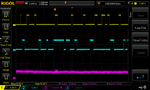
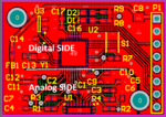
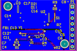
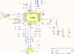
I am designing a magneto resistive encoder. For the magneto resistive sensor I am using KMXP5000 sensor, for further signal processing I took IC-TW8 interpolator. The problem I have is the noise in power supply, the noise is only there when IC-TW8 interpolation IC is running, if I reset it the noise disappears. I included the image from oscilloscope, the purple channel is the ripple and noise measurement from power supply. I am measuring same noise if I put probe to GND plane, can someone tell me why ? I included image of PCB top plane so you can see how I designed circuit. I have split ground plane and only power supply trace is passing from digital to analog side of circuit. Is there a way of measuring where the noise come from or how one diagnose such circuit ?

Thanks for any help.
 

Attachments

  • Noise.png
    Noise.png
    55.2 KB · Views: 77
  • PCB.png
    PCB.png
    178.4 KB · Views: 71

Your power supply has high frequency signals and voltage spikes. If it was properly filtered with a capacitor to ground with short leads on this circuit board then it would not have those noises.
But you forgot to show the schematic. You also forgot to show where you connected the ground wire of your 'scope, and where the circuit connects to the ground plane.
 

Hi,

The schematic could help.

And the bottom copper plane of your PCB.

Klaus
 

I cant see any decoupling caps near the main IC, I also second Audiogurus'comments on filtering....
 

Also, I count many nets crossing that split, usually a mistake.

Add decoupling and remove the split in the plane (They are **usually** a bad plan), or at least route things so that all those nets connecting to the bottom edge of the QFN do not cross the split....

And yea, 'scope' probing technique is really important here, it does not take much loop area due to a scope ground clop to pick that sort of hash up.

Regards, Dan.
 

The oscilloscope capture show 19 mVpp, that's really not much noise.

I presume it's a two-layer PCB. We would need to see the bottom side to determine the ground quality. At first sight there should be more qround vias.
 

Hi,

It was measurement error I was using standard ground clip for grounding the oscilloscope probe and it was picking up noise. Then I changed to the spring type and could make the proper measurement.

I would still like to get suggestions on improving my design so I am including bottom PCB plane and schematic. If any one could check it and tell me what to correct.

Thanks.
 

Attachments

  • BOTTOM.png
    BOTTOM.png
    103.9 KB · Views: 68
  • SCHEMATIC.png
    SCHEMATIC.png
    89.9 KB · Views: 71

I doubt that the split ground brings advantage, according to my experience it's more likely to increase noise level. You may want to short it with multiple wires and check the effect. In the rare cases where connecting AVSS and DVSS to different planes is reasonable, manufacturers suggest to short them directly at the respective IC.

EMC-wise, a continuous ground plane is always preferred.

The bottom view clarifies the missing ground via point, e.g. near C16 and C17.

Does the IC have an exposed pad? If so, what's the datasheet specification about it's connection?
 

Hi,

I doubt that the split ground brings advantage, according to my experience it's more likely to increase noise level.

I have good experience with split GND planes. For sure the "split" has to be at the correct position.
Especially where pulsed currents are on the same PCB with sensitive analog circuitry.

I try to keep the analog GND plane quiet while the pulsed current (loops) are on the other side.

Klaus
 

Status
Not open for further replies.

Part and Inventory Search

Welcome to EDABoard.com

Sponsor

Back
Top