MISU.RSG
Member level 1
Hi dears.
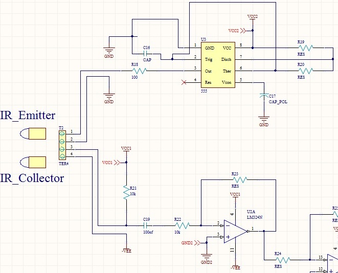
I designed a circuit for sending and receiving infrared signal. its range is about 1 meter but it have to pass 2 7 millimeter wholes. I used common 5mm IR emitter and receiver diodes. VCC2 and VCC1 are 12V for ground1.
IC's part number is NE555 and its frequency set on 7kHz. 555 just produce a simple continuous pulse. pick voltage on LED is about 1.35V and the voltage that drop out over R18 is about 9.75V. LED is 5mm IR once.
if other parameter is necessary please tell me.
may you please check my my circuit and see if I have weakness in circuit?
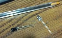
distance of sensors(emitter and receiver) and boards are about 2 meters. I attached image of sensors.
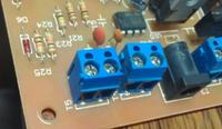
I don't have any problem with 555 and emitter diode because when I check it with phone`s camera I see that it work.. but in emitter part after some days or months system can not sense any signal.at this time, I touch terminals(I attached its image too) or I open wires and close them again, problem solved.
or coupler capacitor C16 brake and pass DC signal.
any idea?
thanks all.
I designed a circuit for sending and receiving infrared signal. its range is about 1 meter but it have to pass 2 7 millimeter wholes. I used common 5mm IR emitter and receiver diodes. VCC2 and VCC1 are 12V for ground1.
IC's part number is NE555 and its frequency set on 7kHz. 555 just produce a simple continuous pulse. pick voltage on LED is about 1.35V and the voltage that drop out over R18 is about 9.75V. LED is 5mm IR once.
if other parameter is necessary please tell me.
may you please check my my circuit and see if I have weakness in circuit?
distance of sensors(emitter and receiver) and boards are about 2 meters. I attached image of sensors.
I don't have any problem with 555 and emitter diode because when I check it with phone`s camera I see that it work.. but in emitter part after some days or months system can not sense any signal.at this time, I touch terminals(I attached its image too) or I open wires and close them again, problem solved.
or coupler capacitor C16 brake and pass DC signal.
any idea?
thanks all.