nishal
Advanced Member level 4
pic32 tft
Hi all,
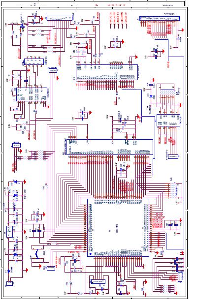
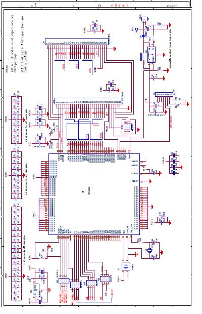
I am using PIC32 to control TFT lcd (800x480) via Epson display driver S1D13742. Everything works well except all the displayed images are mirrored.
Please point out a solution.
Thanks in advance
- Nishal
Hi all,
I am using PIC32 to control TFT lcd (800x480) via Epson display driver S1D13742. Everything works well except all the displayed images are mirrored.
Please point out a solution.
Thanks in advance
- Nishal