Continue to Site

Welcome to EDAboard.com

Welcome to our site! EDAboard.com is an international Electronics Discussion Forum focused on EDA software, circuits, schematics, books, theory, papers, asic, pld, 8051, DSP, Network, RF, Analog Design, PCB, Service Manuals... and a whole lot more! To participate you need to register. Registration is free. Click here to register now.

Mikro C CODE for boost converter

Status
Not open for further replies.

Thabisa

Newbie level 3
Joined
Feb 24, 2015
Messages
3
Helped
0
Reputation
0
Reaction score
0
Trophy points
1
Activity points
19
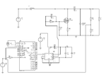
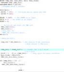
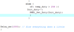
The input voltage can be changed from 12v all the way to 18v .The objective is to maintain a constant voltage output of 24v using the pic Micro-controller.The duty cycle of the PWM will be changed automatically by the value obtained.The code that has been posted doesn't work
 

Attachments

  • LmNQv.png
    LmNQv.png
    13.3 KB · Views: 99
  • Capture.PNG
    Capture.PNG
    32.5 KB · Views: 99
  • Capture2.PNG
    Capture2.PNG
    6 KB · Views: 89

I assume it is a student exercise, not intended for a real product.

Do you have real hardware or are you trying to simulate?

What crystal frequency are you using?

A few things from a quick look.

Value of R5, 470ohm, is far too high. With 70ohm load that is not going to work.
I assume that resistor is intended to prevent the mosfet burning when the software
turn it on for too long.
Perhaps intended to be 4.7ohm resistor with a high power rating. If you use a bench
power supply with a current limit of 1amp then you could a 5watt resistor, or combine
some smaller resistors eg ten 0.5watt 47ohm in parallel.


If you have long wires from the 12volt psu, you will want a smoothing capacitor near
L1 and the mosfet. It will need good layout for the parts of the circuit with fast switching.

It may be easier to get started if you make COUT a much higher value. 12.5uF is a bit low.

Your output current is 0.26A, when COUT is holding up the output voltage between pulses,
we can calulate that the voltage will drop 1volt (eg 18volt to 17volt) in 0.00005 seconds

You will need a fairly fast switching rate to not have huge output ripple with cout=12.5uF

The 16f877 datasheet suggest feeding an ADC pin from a source impedance of 2500ohm max,
source impedance of voltage divider with 138K resistor is much higher.
 

indeed it is a student exercise.A prototype has to be made at a later stage
 

Status
Not open for further replies.

Part and Inventory Search

Welcome to EDABoard.com

Sponsor

Back
Top