Continue to Site

Welcome to EDAboard.com

Welcome to our site! EDAboard.com is an international Electronics Discussion Forum focused on EDA software, circuits, schematics, books, theory, papers, asic, pld, 8051, DSP, Network, RF, Analog Design, PCB, Service Manuals... and a whole lot more! To participate you need to register. Registration is free. Click here to register now.

[SOLVED] Microwave detection circuit verification

Status
Not open for further replies.

pralay.p

Newbie level 4
Joined
Apr 30, 2021
Messages
7
Helped
0
Reputation
0
Reaction score
0
Trophy points
1
Activity points
77
Dear all,

I want to develop a circuit which can detect electromagnetic waves (radio wave, microwaves.)

This circuit will just act as a tamper detect and not physically measure/compute the radiation.

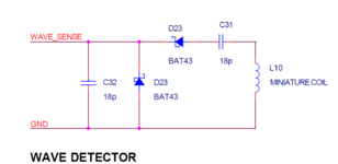
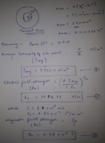
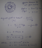
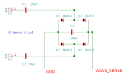
I have designed the circuit using a toroid ring and a few Schottky diodes.

The calculation formulas and schematic diagram are in the attachment.

After testing the circuit, I'm not getting any output.

Hence, I wanted to get the circuit as well as the calculation part of it verified.

Please note that the WAVE_SENSE signal in the design is connected to a 10-bit ADC of a microcontroller.

Anyone related, Please help me achieve this task.

Thanks in advance.
 

Attachments

  • Wave_detector_Screenshot 2021-04-30 122841.png
    Wave_detector_Screenshot 2021-04-30 122841.png
    26 KB · Views: 105
  • Formula_page1_2021-04-30 144736.png
    Formula_page1_2021-04-30 144736.png
    608.5 KB · Views: 117
  • Formula_page2_ 2021-04-30 144836.png
    Formula_page2_ 2021-04-30 144836.png
    478.3 KB · Views: 111

Don't use a toroid, they are a particularly bad choice because they are relatively immune to waves from outside the core. In fact they are normally used because they don't 'leak' magnetism but the same applies the other way around.

What frequencies are you looking for? The 'pick-up' really needs to be optimized for the range you are interested in. If you want a wide range, add an antenna at the input but don't expect the toroid to pick things up by itself.

Brian.
 

This does not work because very low level RF and Microwave Signal Fields cannot be sensed by bulky Toroidal Inductor.
In fact, Field Measurements in every relative Frequency Band must be separately done.Because sensing element and its associated circuit will exhibit different responses for each frequency band.That's why it's not possible to detect RF Fields form kHz band to Microwave bands.
A large assortment of simple rf detector circuits can be found via internet search. Many have a long antenna wire instead of the inductor used in your schematic.
Does it mean the toroid is actually obstructing the microwaves and if i replace it with antennas cum wire it may actually work right??
How about the attached schematic.
The normal diodes are also replaced with high frequency diodes.
And if i solder these SMD components on a PCB this might work right?
Don't use a toroid, they are a particularly bad choice because they are relatively immune to waves from outside the core. In fact they are normally used because they don't 'leak' magnetism but the same applies the other way around.

What frequencies are you looking for? The 'pick-up' really needs to be optimized for the range you are interested in. If you want a wide range, add an antenna at the input but don't expect the toroid to pick things up by itself.

Brian.
 

Attachments

  • N6bxW.png
    N6bxW.png
    8.2 KB · Views: 104

Better - but not much better.

What you should aim to achieve is a low DC resistance across the antenna (to prevent static damage) but a high AC impedance AT THE FREQUENCY OF INTEREST. You can then measure the AC level with a simple half wave rectifier. Using a bridge isn't particularly useful, especially if you are looking for low level signals because you have two diodes in series, whichever polarity you look at, that means two voltage drops across their PN junctions and therefore less voltage recovered.

Placing the inductor across the antenna points with a single diode rectifier will work better but beware that the inductor needs to be selected for the frequency band you want to sense. You will get broader frequency coverage but less sensitivity if you use a resistor instead.

Also note that unless you are close to the signal source, the output will be quite low. Levels typically picked up from commercial masts is in the uV range so you may need amplification before sending the voltage to your ADC, even if it is a 10-bit one.

Brian.
 

you CAN use a loop of wire as a magnetic sensor. and can use a short length of wire as an electric field sensor.
Neither will be super efficient at coupling to the microwave energy unless the frequency of interest is a single tone, AND you tune the antenna to that one frequency.

if you gave us some idea of the exact frequencies you are trying to detect, we could comment more. you might be able to use a pre-tuned chip antenna, for instance

btw, your 18 pf capacitor should probably be bigger. maybe 47 pf or 100 pf.
 

Better - but not much better.

What you should aim to achieve is a low DC resistance across the antenna (to prevent static damage) but a high AC impedance AT THE FREQUENCY OF INTEREST. You can then measure the AC level with a simple half wave rectifier. Using a bridge isn't particularly useful, especially if you are looking for low level signals because you have two diodes in series, whichever polarity you look at, that means two voltage drops across their PN junctions and therefore less voltage recovered.

Placing the inductor across the antenna points with a single diode rectifier will work better but beware that the inductor needs to be selected for the frequency band you want to sense. You will get broader frequency coverage but less sensitivity if you use a resistor instead.

Also note that unless you are close to the signal source, the output will be quite low. Levels typically picked up from commercial masts is in the uV range so you may need amplification before sending the voltage to your ADC, even if it is a 10-bit one.

Brian.
Thankyou so much Brian for your suggestions.
I will keep these things in mind.
I want to implement these changes gradually though, after first testing the circuit which I have.
 

you CAN use a loop of wire as a magnetic sensor. and can use a short length of wire as an electric field sensor.
Neither will be super efficient at coupling to the microwave energy unless the frequency of interest is a single tone, AND you tune the antenna to that one frequency.

if you gave us some idea of the exact frequencies you are trying to detect, we could comment more. you might be able to use a pre-tuned chip antenna, for instance

btw, your 18 pf capacitor should probably be bigger. maybe 47 pf or 100 pf.
I want to detect frequency as low as 10kHz to 2.5GHz.
 

I want to detect frequency as low as 10kHz to 2.5GHz.
good luck!
the only way i have seen such a wide frequency range done is with a single loop, shorted to a ground plane on one side, and the other end of the loop connected to a broadband CURRENT amplifier. It is a low impedance non-resonant structure, and will handle that frequency range, as long as the loop does not get too big electrically at 2.5 Ghz.

it is NOT a very efficient way to detect RF fields though. I would use thick copper conductor for the loop
 
Last edited:

Status
Not open for further replies.

Part and Inventory Search

Welcome to EDABoard.com

Sponsor

Back
Top