Continue to Site

Welcome to EDAboard.com

Welcome to our site! EDAboard.com is an international Electronics Discussion Forum focused on EDA software, circuits, schematics, books, theory, papers, asic, pld, 8051, DSP, Network, RF, Analog Design, PCB, Service Manuals... and a whole lot more! To participate you need to register. Registration is free. Click here to register now.

Microcontroller malfunction in industrial environment

Status
Not open for further replies.

abc_de

Full Member level 5
Joined
Jan 9, 2014
Messages
243
Helped
11
Reputation
22
Reaction score
11
Trophy points
1,298
Location
Ludhiana ਪੰਜਾਬ
Activity points
2,939
Hi ..
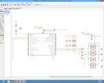
My microcontroller has stopped working and has gotten out of order while using in harsh industrial environment. i am driving circuit by +24v SMPS (OMRON) and using Line filter (COMMON MODE CHOCK) for 220v.
in circuit i have use decoupling caps .1uf with each IC and 10uf Bypass caps.

please guide me how i can avoid this problem
 

Please post your Schismatics
 
  • Like
Reactions: abc_de

    abc_de

    Points: 2
    Helpful Answer Positive Rating
The improvement of your design should be done in two separate directions:
1. Hardware improvements - to minimize the impact of external noises to the controller:
- better schematic
- better PCB design
- better mechanical design

2. Firmware improvements. Whatever you do you could never guarantee that the controller will never hang or misbehave but you could do many improvements to minimize the impact of such events or even to make them completely invisible:
- watch dog and brown out detection are "must have"
- thread counters placed on many critical places to guarantee the correct sequence of execution. If threard counter is incorrect - start recovering preferably by doing hardware reset.
- make additional copies of the critical variables in your code and do special processing
- special software architecture to recover immediately and to make the misbehaviour minimal in time

In our company we struggled a lot with such noises, it came out that by doing 1 and 2 you could virtually make the design free of hanging. Even if it's affected from the noises this will be invisible for the user.

Kind regards,
Luben
 
  • Like
Reactions: abc_de

    abc_de

    Points: 2
    Helpful Answer Positive Rating
And watch out for ground current loops
I once had a robot try to eat someone alive just because they had
connected the shielding of a simple rs232 cable to ground at both ends
instead of just one end.
 
  • Like
Reactions: abc_de

    abc_de

    Points: 2
    Helpful Answer Positive Rating
Please view the schematic for more improvements
 

Attachments

  • cpu.jpg
    cpu.jpg
    201.6 KB · Views: 107
  • input side.jpg
    input side.jpg
    195.9 KB · Views: 100
  • output side.jpg
    output side.jpg
    202.8 KB · Views: 102

Utilizing embedded microcontrollers for industrial applications requires special attention given the harsh
and noisy environment. Going from a supply voltage as low as +1.5V or +3.3V to the +24V industrial world
requires careful design decisions and dedicated solutions to achieve safe and reliable operation.

First read this links

https://www.ichaus.biz/upload/pdf/WP1en_MCU Interface to Industrial World_08082012.pdf

https://www.ichaus.biz/upload/pdf/WP1en_MCU Interface to Industrial World_08082012.pdf

https://www.ichaus.biz/appnote_industrial
 
Last edited:
  • Like
Reactions: abc_de

    abc_de

    Points: 2
    Helpful Answer Positive Rating
Please view the schematic for more improvements
Opto isolation is meaningless if both sides share the same power supply...

On the other hand, you don't necessarily need isolation to block interferences. It's more a matter of suitable power and ground layout, supply bypassing, transient suppression at supply lines and external in- and outputs.
 
  • Like
Reactions: abc_de

    abc_de

    Points: 2
    Helpful Answer Positive Rating
Opto isolation is meaningless if both sides share the same power supply...

I would disagree for opto isolation - it's proved to be the best and most reliable way to prevent the noises to come in. For sure it it would be much better if they are galvanically isolated but even with the current schematic it will be achieved significant noise immunity improvement.

Unfortunately it's not only about schematic - a good schematic with bad PCB rooting can compromise the noise performance. There is an endless list of tips and tricks how to make one PCB more noise immune. If you post the PCB design we could highlight some weak places.

Kind regards,
Luben
 

please also guide how to develop good firmware for robust, noisy environment
 
Last edited:

Since I mentioned rs232 I should perhaps point out it isnt a good idea to use it in noisy environments or on long runs
and of course I also mentioned current loops - but that phrase does have another use - the answer to not using rs232 -
I'd recommend having a read here : https://en.wikipedia.org/wiki/Current_loop to start with.
 
  • Like
Reactions: abc_de

    abc_de

    Points: 2
    Helpful Answer Positive Rating
As previously mentioned, power and ground layout is the key. It's effectively impossible to make a transient resistant design on a single side PCB.
 

Hi,

You need to connect the GND of the processor unit to only one point to the other ground wires in order to avoid currents flowing through these lines. The best way top achieve this is to redraw the schematic by using two different grounds (GND1 and GND2 for example). GND1 is only serving the processor where GND2 is for the other part. Between GND1 and GND2 you place a small resistor and this will guarantee that you connect them in a single point.

The main potential problem is to have currents flowing through the ground lines which can compromise the processor stability. Also as I said you need to remake the firmware and to put some features that prevents the processor form hanging. Don't forget BOD to be ON.

Kind regards,
Luben
 

Status
Not open for further replies.

Similar threads

Part and Inventory Search

Welcome to EDABoard.com

Sponsor

Back
Top