Continue to Site

Welcome to EDAboard.com

Welcome to our site! EDAboard.com is an international Electronics Discussion Forum focused on EDA software, circuits, schematics, books, theory, papers, asic, pld, 8051, DSP, Network, RF, Analog Design, PCB, Service Manuals... and a whole lot more! To participate you need to register. Registration is free. Click here to register now.

Micro C programming with Atmega 32

Status
Not open for further replies.

bijus

Member level 1
Joined
Apr 11, 2013
Messages
34
Helped
0
Reputation
0
Reaction score
0
Trophy points
1,286
Location
India
Activity points
1,534
Hi,

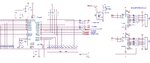
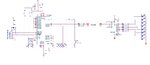
Can anybody help me to inter phase Shift registers to Atmega 32A.

i am a beginner and currently using microc for programming..

shift register is HEF4094.
 

show what you have already designed for 4094 to atmega32 interfacing ,
indicating the pin numbers/signal names.
 

Hi,

Yes, we can help.
But how? What have you done so far? Did you read the datasheet? Did you understand it?

We won't provide complete code, but we will help you to correct your code.

Btw:
what do you want to achieve?
What data transfer rate do you need?
Why especially "HEF" CMOS series?
What power supply / voltage?
Show your circuit.

Klaus
 

Thanks for your reply.
I have got some ideas from tutorial and google links. i will get back to you once i fed up any where....
Thanks for your time...
 

show what you have already designed for 4094 to atmega32 interfacing ,
indicating the pin numbers/signal names.

hi,

pls see the below code i have done.

Actually i need to ON and OFF one LED through 4094 by pressing a switch.
but what is happening right now, along with the LED, the other bits also effected.
How can i do it without effecting the other bits. pls help me to do this.....

I am a beginner
===================

Code:
bit  oldstate1,count1;
int i;
int beep();
int privacy_state();
int privacy_state1();

int privacy[] = {1,0,0,0,0,0,0,0};   // privacy byte code for shift register

void beep()
      {
        Delay_ms(50);               // initial delay
        PORTD |= (0x01<<0);     // BEEP ON
        Delay_ms(200);            // cutoff delay
        PORTD &=~(0x01<<0);  // BEEP OFF
      }

void privacy_state()
   {
      for(i=0;i<=7;i++)
       {
          if (privacy[i]==1)
           {
              beep();
              PORTA|=(0x01<<3);    // data on
              delay_ms(1);
           }

          if (privacy[i]==0)
           {
              PORTA&=~(0x01<<3);    // data off
              delay_ms(1);
            }

          PORTA |= (0x01<<1);   // clk on
          delay_ms(1);
          PORTA &=~(0x01<<1);   // clk off
          delay_ms(1);
       }
          delay_ms(1);
          PORTA |= (0x01<<2);   // str on
          delay_ms(1);
          PORTA &=~(0x01<<2);   // str off
          delay_ms(1);
    }

void privacy_state1()
    {
       for(i=0;i<=7;i++)
         {
          if (privacy[i]==1)
            {
              PORTA&=~(0x01<<3);    // data off
              delay_ms(1);
            }

          if (privacy[i]==0)
            {
              PORTA|=(0x01<<3);    // data on
              delay_ms(1);
             }
          PORTA |= (0x01<<1);   // clk on
          delay_ms(1);
          PORTA &=~(0x01<<1);   // clk off
         delay_ms(1);
        }
          delay_ms(1);
          PORTA |= (0x01<<2);   // str on
          delay_ms(1);
          PORTA &=~(0x01<<2);   // str off
          delay_ms(1);
     }

void main() 
  {
    DDA0_BIT = 1;              // DATA
    DDA1_BIT = 1;              // CLK
    DDA2_BIT = 1;              // STR
    DDC6_BIT = 1;              // DND LED
    DDD0_BIT = 1;              // BEEP OUT

    PORTD4_BIT = 1;            //  DND SW

    oldstate1 = 0;
 do
    {
//=============================== PRIVACY =====================================
       {
        if (Button(&PIND, 4, 1, 1))
          {
            oldstate1 = 1;
          }
        if (oldstate1 && Button(&PIND, 4, 1, 0))
          {
           privacy_state();
           count1++;
          }
          if (count1==1)
          {
           privacy_state1();
          }
       }
//=============================================================================
  }
while (1) ;
 }
 

attach a circuit schematic showing the atmega32 and 4094
connection . (show the reqd port signals and 4094)

Where do you control OE of 4094 in your code?

What do you ultimately want atmega to do?
Give a brief description of requirement .
 

Hi,
i am trying to study the programming.

i have already a working hardware with atmega 32 and 4094. it was programmed by someone else.

That`s why atmega.....

OE is directly connected to +5V.


Port A1 as Clock
Port A2 as Strobe
Port A3 as Data

Port D4 as Switch

LED connected in all outputs of 4094 (Q0 to Q7).
 

Hi,

Textual descriptions are always hard to understand and almost always incomplete.
Thus we ask for a schematic. Hand made is O.K.
And when doing any design you should already have one.

Klaus
 

The Schematic diagram is attached.

Data strobe clock is changed as per below....

Port A1 as Clock
Port A2 as Strobe
Port A3 as Data

Port D4 as Switch _ one press "ON", one Press "OFF".

LED connected in all outputs of 4094 (Q0 to Q7).

Don`t consider the other circuits. I am just using the board for my easiness.

Right now i modified my code like this....

Its working now but having some problem by adding more input ports with the same function (((( void data_Shifting(void) ))))

==========================================================================
Code:
unsigned char oldstate1,count1,control_byte;
void beep();
void privacy_sw();
void data_Shifting();

void beep()
   {
      Delay_ms(50);               // initial delay
      PORTD |= (0x01<<0);     // BEEP ON
      Delay_ms(200);             // cutoff delay
      PORTD &=~(0x01<<0);   // BEEP OFF
   }
void privacy_sw()
  {
    if (count1==0)
     {
      control_byte = control_byte | 0x01; // 00000001
     }
    if (count1==1)
     {
      control_byte = control_byte & 0xFE; //  11111110
     }
   }


void data_Shifting(void)
  {
   unsigned char temp_loop,rotate,temp_data,temp_data1;   // declaring privatly in side the program

       PORTA2_BIT = 0;              // str off
       
       privacy_sw();

       temp_data=control_byte; // 0XF0;

   for(temp_loop=0;temp_loop<8;temp_loop++)
     {
        if (temp_data&0x80)
        {
            PORTA3_BIT = 1;     // data on
        }
        else
        {
            PORTA3_BIT = 0;     // data off
        }
          temp_data<<=1;

             PORTA1_BIT = 1;     // clk on
             delay_us(10);
             PORTA1_BIT = 0;     // clk off
      }
         PORTA2_BIT = 1;        // str on 3
  }

void main()
{
    DDA1_BIT = 1;              // CLK
    DDA2_BIT = 1;              // STR
    DDA3_BIT = 1;              // DATA
    DDC6_BIT = 1;              // DND LED
    DDD0_BIT = 1;              // BEEP OUT
    DDD0_BIT = 0;              // KTH OUT
    DDC7_BIT = 1;              // SER LED
    DDD3_BIT = 1;              // FUNCTIONAL led

    PORTD4_BIT = 1;            //  DND SW
    PORTD7_BIT = 1;            //  SER SW

    oldstate1 = 0;
    oldstate2 = 0;

control_byte = 0;
while(1)
 {
//=============================== PRIVACY =====================================
       {
        if (Button(&PIND, 4, 1, 1))
          {
            oldstate1 = 1;
          }
        if (oldstate1 && Button(&PIND, 4, 1, 0))
         {
            oldstate1 = 0;
            beep();
            PORTC |=  (0x01<<6);    // DND ON
            data_Shifting();
            count1++;
            if(count1==2)
            {
            count1=0;
            }
         }
        if (count1==1)
         {
           PORTC &=~ (0x01<<6);       // DND OFF
         }
       }
//=============================================================================
    
    }

 }
 

Attachments

  • Circuit Diagram.jpg
    Circuit Diagram.jpg
    189.5 KB · Views: 130

Hi,

* The schematic is a mess
* Some part values don't make sense.
* Still unclear how the LED is connected (whether HIGH or LOW activates the LED)
* text says HEF4094, schematic says CD4094, neither one is suitable to drive LEDs

Klaus
 

Hi,

* The schematic is a mess
* Some part values don't make sense.
* Still unclear how the LED is connected (whether HIGH or LOW activates the LED)
* text says HEF4094, schematic says CD4094, neither one is suitable to drive LEDs

Klaus


Hi

Schematic corrected. its a working PCB, i am only using a part of it..
 

Attachments

  • 4094-2.jpg
    4094-2.jpg
    105.5 KB · Views: 111

change:


Code C - [expand]
1
2
3
4
temp_data<<=1;
             PORTA1_BIT = 1;     // clk on
             delay_us(10);
             PORTA1_BIT = 0;     // clk off


as:


Code C - [expand]
1
2
3
4
5
PORTA1_BIT = 0;   
             temp_data<<=1;
             PORTA1_BIT = 1;     // clk on
             delay_us(10);
             PORTA1_BIT = 0;     // clk off

 
Last edited by a moderator:

change:


Code C - [expand]
1
2
3
4
temp_data<<=1;
             PORTA1_BIT = 1;     // clk on
             delay_us(10);
             PORTA1_BIT = 0;     // clk off


as:


Code C - [expand]
1
2
3
4
5
PORTA1_BIT = 0;   
             temp_data<<=1;
             PORTA1_BIT = 1;     // clk on
             delay_us(10);
             PORTA1_BIT = 0;     // clk off


Hi,

Thanks for your valuable suggestion.

its fine initially clk is in off position....

Thanks..
 

Status
Not open for further replies.

Similar threads

Part and Inventory Search

Welcome to EDABoard.com

Sponsor

Back
Top