zerodegreec
Junior Member level 3
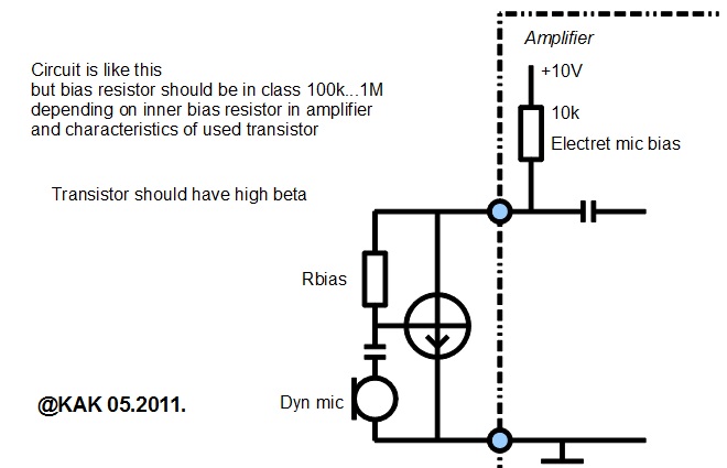
I have a simple circuit that enables me to use a Dynamic Mic on a system designed for a Electret mic. It uses 3 parts.
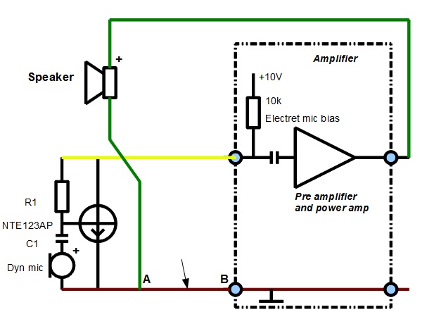
I am limited for the # of wires in and out of my pre-amp. The amp I am connecting to uses 3 wires (shares the neg of the Mic and speaker). my input has 4 wires (2 for each the mic and Speaker)
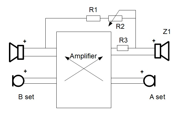
My problem is that I would like to have a little bit of feedback from the mic to the speaker. Right now I get none at all. Any ideas of how I could figure this out?
**broken link removed**
BTW the application is for a communication setup inside a headset used in a very loud environment. When I talk I would like to hear my own voice (not very much). right now its just silence and its kind of weird talking without hearing yourself even a little bit.
Thanks for any help you can throw my way.
I am limited for the # of wires in and out of my pre-amp. The amp I am connecting to uses 3 wires (shares the neg of the Mic and speaker). my input has 4 wires (2 for each the mic and Speaker)
My problem is that I would like to have a little bit of feedback from the mic to the speaker. Right now I get none at all. Any ideas of how I could figure this out?
**broken link removed**
BTW the application is for a communication setup inside a headset used in a very loud environment. When I talk I would like to hear my own voice (not very much). right now its just silence and its kind of weird talking without hearing yourself even a little bit.
Thanks for any help you can throw my way.