Continue to Site

Welcome to EDAboard.com

Welcome to our site! EDAboard.com is an international Electronics Discussion Forum focused on EDA software, circuits, schematics, books, theory, papers, asic, pld, 8051, DSP, Network, RF, Analog Design, PCB, Service Manuals... and a whole lot more! To participate you need to register. Registration is free. Click here to register now.

[SOLVED] [Mentor Graphics] Simulation of 8-bit ALU CMOS to get the waveform?

Status
Not open for further replies.

Siong Hui

Newbie level 6
Joined
May 17, 2021
Messages
11
Helped
0
Reputation
0
Reaction score
0
Trophy points
1
Activity points
86
Hi,

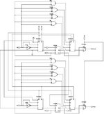
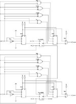
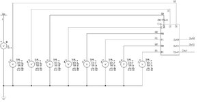
I doing a project about designing 8-bit ALU CMOS using Mentor Graphics. So, I using a hierarchical method of 2-bit ALU to form the 8-bit ALU. The simulation of 2-bit ALU is successfully, but why my simulation of 8-bit ALU is failed. For the 8-bit ALU CMOS, I need to spend one to two hours to simulate it, but the outcome is simulation failed. Does anyone have ideas on how to solve it?

The transcript of the simulation is attached below.
 

Attachments

  • 8-bit ALU CMOS sim_transcript.txt
    109.5 KB · Views: 171

Arithmetic Logic Unit (ALU).
Your log has these specs:
nb of components: 2101
nb of nodes: 7302

If your project uses analog components , then it's a major challenge for a simulator to work with thousands of components and thousands of nodes. This could be a situation where you have to choose whether to
make the analog side complex and the digital side simple, or vice versa. It may be too much to ask for both analog and digital complexity in one simulation.

If you wish to examine electrical behavior of ALU circuitry, then you may have to settle for a simple 2-bit simulation. Did you try an arrangement somewhere in the middle (say, a 4-bit ALU)?

Or instead if you wish to examine the logic performed in an ALU, then it's more practical for you to choose digital logic component models... that is, the kind that portray the function of logic gates, rather than require you pay attention to power supplies and ground connections. (Many errors in your log have to do with floating gates, paths to ground, power supply connections.)
 

For the 4-bit ALU, I already try, but still cannot simulate it. The highest bit that I can simulate is 2-bit ALU CMOS. I will attach the schematic diagram of the 2-bit ALU below.

So, can your guys guide me on how to solve the problem?
 

Attachments

  • 2-bit ALU.JPG
    2-bit ALU.JPG
    49 KB · Views: 227

Your schematic has many wires joining, creating many nodes. We know this is not an error (electrically speaking), and the simulator catalogues all nodes and branches at the beginning of a run.

Then it has to calculate each frame, which means finding how much current goes through each branch, and finding volt levels at each node. I think the simulator would have an easier chore if you give each digital input its own connection to the source.

At present you have many cases of a source fanning out to several inputs. Current flow is miniscule yet the simulator must still use cpu cycles as it attempts to calculate the amount of current in all those branches, and the volt levels at those many nodes.
 

May I know, each digital input its own connection to the source means that I need to separate the source of the 2-bit ALU CMOS? So, I need to create a new source for the second ALU and connect the wire to the new source, right? This concept is correct?
 

May I know, is this correct? I already simulate this schematic diagram, but the simulation result is failed.
 

Attachments

  • 2-bit ALU CMOS.JPG
    2-bit ALU CMOS.JPG
    81.2 KB · Views: 209

Try running the top half separately. Feed the inputs with signals that are acceptable volt levels to be recognized definitely as high or low. (And avoid disallowed combinations of signals.)

See if the outputs behave as you expect them to. Look at the report log to figure out what you're doing right (if it succeeds) or wrong (if it fails).

Also test the bottom half by itself.

You may need to revise a component model. You may need to test devices individually (logic gate, adder, multiplexer, etc.).

Can you find an equivalent (or similar) circuit among the Mentor Graphics sample circuits? Or simpler working circuit that you can build on?
 

I already test the devices individually before I combine them to form 1-bit ALU. The waveform for the devices is correct. Now, the simulation of 2-bit ALU is no problem. So, even I run and test the simulation for 1-bit ALU, it still can successful obtain the waveform. When I add one more bit for ALU, the simulation is failed.
 

This is only speculation... You appear to have several stages where a later stage has some of its inputs undefined, until an earlier stage generates a definite output. This is not an error (electrically speaking), however as for the robot-like simulator it has to start a run with undefined states at several inputs. (Similar to floating inputs.) Therefore it has trouble achieving convergence during the first few iterations.

We'd expect such a situation to have a workaround built into the simulator's algorithms, so it doesn't get bogged down by such a simple thing. And maybe it does contain safeguards...
But just in case your schematic causes difficulty, it might help if you were to install pull-up (or pulldown) resistors at inputs that appear undefined at the start of a run.
 

You might want to look at acquiring veriloga
logic gate models (like from Ken Kundert's web
pages - designers-guide.org ?) and use them
as a stepping-stone to validate your higher
level assembly with efficient simulation, then
substitute transistor level versions.

Of course you'd need a simulator than will
digest veriloga, which is not many of the open
source ones. I'd expect Mentor and know Cadence
to be capable (some assembly required, the veriloga
code has to be fitted up to symbols and so on).
 

This is only speculation... You appear to have several stages where a later stage has some of its inputs undefined, until an earlier stage generates a definite output. This is not an error (electrically speaking), however as for the robot-like simulator it has to start a run with undefined states at several inputs. (Similar to floating inputs.) Therefore it has trouble achieving convergence during the first few iterations.

We'd expect such a situation to have a workaround built into the simulator's algorithms, so it doesn't get bogged down by such a simple thing. And maybe it does contain safeguards...
But just in case your schematic causes difficulty, it might help if you were to install pull-up (or pulldown) resistors at inputs that appear undefined at the start of a run.
So, may I know, what I can do now to solve the problems? Because I still blur about it. These few days, I try to use the standard cells inside the Mentor Graphics to build the ALU, unfortunately, I only manage to run the simulation until 4-bit ALU. The simulation of 8-bit ALU still cannot get the waveform.
 

You might want to look at acquiring veriloga
logic gate models (like from Ken Kundert's web
pages - designers-guide.org ?) and use them
as a stepping-stone to validate your higher
level assembly with efficient simulation, then
substitute transistor level versions.

Of course you'd need a simulator than will
digest veriloga, which is not many of the open
source ones. I'd expect Mentor and know Cadence
to be capable (some assembly required, the veriloga
code has to be fitted up to symbols and so on).
Noted, I will look into it.
 

By the time you build the full 8-bit schematic, it occupies several screens. It may just be too ambitious to ask the simulator to handle.

The simulator has rigid rules in calculating each frame. It has to reach convergence according to those rules. I doubt there's a menu choice by which you can tell it to be satisfied with 'approximate' convergence, or command it to perform ten iterations, display the result no matter what, then go on to the next frame.

As an alternative, there is a feature in some simulators where you can get a small circuit to work (say, a 2-bit ALU), then designate it as a 'block' all in one package with its own icon. (Sort of like creatling your own IC.) It has 2 or 3 inputs, and 2 or 3 outputs, whatever it needs to operate.

The icon takes up small space onscreen. So you can drop 4 of them onscreen and connect one to the next with only a few wires. Does your simulator allow this?
 

There are several options that can change, but I don't know how to modify the options. I put the options in picture below.
For the alternative method, I already change the 2-bit ALU CMOS to the block and simulate it, but the simulation also failed. I also attached the picture of the 2-bit ALU block diagram.
Can your guys help me, if I need to modify the options, which one I need to modify?
 

Attachments

  • Option part 1.png
    Option part 1.png
    437.5 KB · Views: 187
  • Option part 2.png
    Option part 2.png
    430.4 KB · Views: 186
  • 2-bit ALU block diagram.JPG
    2-bit ALU block diagram.JPG
    43.4 KB · Views: 200

It seems to be a fact of life that circuit simulators are not the most cooperative things to deal with. There are some things you can do with them and some things you can't. Most likely you have to go through the error log line by line, and try this or that in order to reduce the number of errors. Since I'm not acquainted with your program I don't know what settings to change.

Work on simpler circuits. Examine where things go wrong or where they go right. In time you should recognize how to get around the errors. Or you may even discover a simulator which works better at this type of project.
 

Status
Not open for further replies.

Part and Inventory Search

Welcome to EDABoard.com

Sponsor

Back
Top