cupoftea
Advanced Member level 5
Hi,
I need to measure inductances on a switch mode transformer. I have no LCR meter. Txfmr has single Pri and split sec.
But i do have a scope, and a DC power source.
I also have a Frequency response analyser....
(Voltech TF2000)
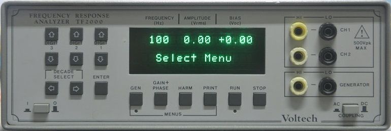
 www.valuetronics.com
(frequency is adjustable from 100Hz to 100Khz and its a sine output)
www.valuetronics.com
(frequency is adjustable from 100Hz to 100Khz and its a sine output)
I only have ceramic caps between 100pF to 470nF available.
Measure L(pri)
For the primary, i put a 12nF ceramic cap in series with the primary, and then fed a 5V peak sine wave to this LC series circuit, from the TF2000. I put the scope across the inductor. I found that the voltage amplitude peaked at approx 31kHz. As such , i calculate L(pri) to be approx 2.2mH.
Measure L(sec)
The secondary is obviously much lower inductance. So to measure L(sec) i put whole sec oil in parallel with a 470nF ceramic capacitor. I then put a 150R in series with this LC. I then put the scope across the LC. I then instantaneously 'tapped' 5VDC across the R--L//C.
...The resulting oscillation had T = 32us. This gives total L(sec) of 55.2uH. So each sec half is (55.2/2)uH
Can you think of any better ways to measure these inductances with this kit?
I need to measure inductances on a switch mode transformer. I have no LCR meter. Txfmr has single Pri and split sec.
But i do have a scope, and a DC power source.
I also have a Frequency response analyser....
(Voltech TF2000)
TF2000 Voltech Analyzer
We have used Voltech TF2000 analyzers available. Thousands of model numbers in stock. Sell your test equipment to us too!
www.valuetronics.com
I only have ceramic caps between 100pF to 470nF available.
Measure L(pri)
For the primary, i put a 12nF ceramic cap in series with the primary, and then fed a 5V peak sine wave to this LC series circuit, from the TF2000. I put the scope across the inductor. I found that the voltage amplitude peaked at approx 31kHz. As such , i calculate L(pri) to be approx 2.2mH.
Measure L(sec)
The secondary is obviously much lower inductance. So to measure L(sec) i put whole sec oil in parallel with a 470nF ceramic capacitor. I then put a 150R in series with this LC. I then put the scope across the LC. I then instantaneously 'tapped' 5VDC across the R--L//C.
...The resulting oscillation had T = 32us. This gives total L(sec) of 55.2uH. So each sec half is (55.2/2)uH
Can you think of any better ways to measure these inductances with this kit?