chamanali
Newbie level 4
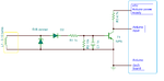
I used below attach Ciruit for inductive pickup coil but a problem is coming to measure the rpm.when i start my motorcycle then arduino does not measure the pulses and it become a blind, does not work..when i keep the inductive coil far from the sparkplug wire then it takes the pulses.
please help me what i do for it.
- - - Updated - - -
REply it fastttt
please help me what i do for it.
- - - Updated - - -
REply it fastttt