Continue to Site

Welcome to EDAboard.com

Welcome to our site! EDAboard.com is an international Electronics Discussion Forum focused on EDA software, circuits, schematics, books, theory, papers, asic, pld, 8051, DSP, Network, RF, Analog Design, PCB, Service Manuals... and a whole lot more! To participate you need to register. Registration is free. Click here to register now.

Measuring Ripple within a passband

Status
Not open for further replies.

uWave

Newbie
Joined
Apr 15, 2015
Messages
2
Helped
0
Reputation
0
Reaction score
0
Trophy points
1,281
Activity points
1,315
Hello everyone,
My colleagues and I are having some debate on the most accurate and correct way to measure passband ripple. We have read literature on the topic and researched it but there is always different opinions and interpretations on this topic. I was interested in getting some input from other professionals hoping to finally put this to bed. Any help, info or direction is greatly encouraged and certainly appreciated on this end.
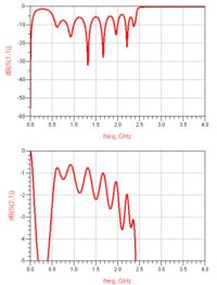
FWIW we design mostly passive chebyshev type filters. There appears to be a big differential in theoretical/design ripple and actual ripple recorded on the test bench once the part is fabricated. There also seems to be some confusion between a "ripple" specification and "passband flatness" or "amplitude variation" specifications. It is my understanding that flatness and ripple are different measurements altogether and that it is possible for one to be compliant and not the other. The biggest question is how one would measure ripple on a network analyzer in real time. Is there a way to measure ripple or is it calculated? I understand ripple to be the same as mismatch loss calculating it from a filters return loss. Basically the better the return loss, the less ripple within the band. It has been suggested that any peak to adjacent peak within the passband is measured as ripple.
I apologize if this topic has been posted previously. I searched and still could not find the answer I was looking for. Anyone who can chime in on this topic is greatly appreciated. Illustrations may be useful also. Thank you!
 

I don't know that there's any difference between flatness and ripple or amplitude distortion or amplitude variation or anything else you might want to call it. They all signify a deviation from a single value. To my understanding there's no difference between saying 'a filter has 3-dB ripples in the passband' or 'a filter has 3-db of amplitude variation in the pass band'.
 

Hello everyone,
My colleagues and I are having some debate on the most accurate and correct way to measure passband ripple. We have read literature on the topic and researched it but there is always different opinions and interpretations on this topic. I was interested in getting some input from other professionals hoping to finally put this to bed. Any help, info or direction is greatly encouraged and certainly appreciated on this end.
FWIW we design mostly passive chebyshev type filters. There appears to be a big differential in theoretical/design ripple and actual ripple recorded on the test bench once the part is fabricated. There also seems to be some confusion between a "ripple" specification and "passband flatness" or "amplitude variation" specifications. It is my understanding that flatness and ripple are different measurements altogether and that it is possible for one to be compliant and not the other. The biggest question is how one would measure ripple on a network analyzer in real time. Is there a way to measure ripple or is it calculated? I understand ripple to be the same as mismatch loss calculating it from a filters return loss. Basically the better the return loss, the less ripple within the band. It has been suggested that any peak to adjacent peak within the passband is measured as ripple.
I apologize if this topic has been posted previously. I searched and still could not find the answer I was looking for. Anyone who can chime in on this topic is greatly appreciated. Illustrations may be useful also. Thank you!

Your question is rather system than filter problem.
There are various filter-response models, from maximally-flat Butterworth, over moderate-ripple Chebyshev, to higher-ripple elliptic.
Those models offer steep or not-so-steep skirts, low pass-band loss and other features. If properly tuned, the pass-band ripple is kept under limits (say 0.1 to 0.5 dB peak).
A system application defines what ripple can be tolerated. Often it depends on modulation type. In radiometers, 0.1 dB may be considered appropriate.
Once I had an interesting problem, to tune Chebyshev iris filters for a perfect phase match in a three-channel phased-array radar. There was some ripple but more important was to tune three filters so that their poles and zeros coincide. The system was quite demanding for phase response, so I spent a long time to make it work. It may be one example where the ripple alone may not be important so much as its peaks and valleys precisely located.
 

each system has its own specific needs. Lets say your IF processing bandwidth was 50 MHz. in that case, you would not really care that much what the ripple was beyond +/- 25 MHz.

If you had a communications system...you might not be so concerned about the peak to peak ripple so long as most of the ripple followed a parabolic path (since that does not cause that much intersymbol interference).

So I would suggest you tailor your ripple specification to exactly what the system requirements are.
 

This thread seems to have taken a wild turn off into the weeds. If your original question was, or still is, "correct way to measure passband ripple", then the answer is simple.
1) Connect a sweep generator to the input (or manually sweep a function generator and make measurements at specific points)
2) Set the limits of the sweep generator to cover your passband
3) Measure the output vs frequency. (You can use an oscilloscope or spectrum analyzer)
 

If the question is about "the most accurate and correct way to measure passband ripple", the answer is very simple.
Use a network analyzer (whatever scalar or vector) and you will get the answer, with higher accuracy than any other method.
 

One of these threads where the OP has a better understanding of the topic than those who try to answer. :|

I don't know that there's any difference between flatness and ripple or amplitude distortion or amplitude variation or anything else you might want to call it. They all signify a deviation from a single value. To my understanding there's no difference between saying 'a filter has 3-dB ripples in the passband' or 'a filter has 3-db of amplitude variation in the pass band'.

I would see a difference:

A real filter does have insertion loss from conductor losses and dielectric losses, even if perfectly matched, and that loss increases with frequency. But that insertion loss is not ripple. I would understand ripple as the extra amount of insertion loss that is caused by reflection, thus changing with frequency in a non-monotonic way -> ripple.

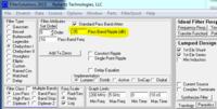
Passband ripple is another way to specify the acceptable/required S11 in filter synthesis, and that value does not include other losses. So from that viewpoint, the OP's question is very valid and most answers completely miss the point.


- - - Updated - - -

Passband ripple spec in filter synthesis, to set acceptable/required return loss:


This is only identical to insertion loss for an ideal, lossless filter (no conductor losses, no dieelectric losses).
 

Actually the total filter insertion loss is the sum of the: loss due to the impedance mismatch at the filter input, the second is due to the mismatch at the filter output, and the third is due to the dissipative loss on each reactive element.
One think have always to remember. Filter ripple depends mainly by two factors. By the filter topology (Chebyshev, Bessel, Butterworth, etc) or by filter input/output match.
 

One of these threads where the OP has a better understanding of the topic than those who try to answer. :|


I would see a difference:

A real filter does have insertion loss from conductor losses and dielectric losses, even if perfectly matched, and that loss increases with frequency. But that insertion loss is not ripple. I would understand ripple as the extra amount of insertion loss that is caused by reflection, thus changing with frequency in a non-monotonic way -> ripple.

Passband ripple is another way to specify the acceptable/required S11 in filter synthesis, and that value does not include other losses. So from that viewpoint, the OP's question is very valid and most answers completely miss the point.


- - - Updated - - -

Passband ripple spec in filter synthesis, to set acceptable/required return loss:


This is only identical to insertion loss for an ideal, lossless filter (no conductor losses, no dieelectric losses).

Volker, you are spot on to my intent. Thank you. If indeed ripple is the amount of extra insertion loss caused by reflection, what would you suggest is the best way to measure this on a network analyzer in a real life situation. Would the simplest method be to record the worst case VSWR and then calculate the ripple from that point essentially giving me the worst case ripple within a specific band? Or is there an actual way to measure this by delta vswr/insertion loss? The end result is hoping to be able to create an automated program that can record this spec. Flatness is very straightforward specifying 2 frequencies and delta worst case/best case insertion loss within that specified range.
 

Would the simplest method be to record the worst case VSWR and then calculate the ripple from that point essentially giving me the worst case ripple within a specific band? Or is there an actual way to measure this by delta vswr/insertion loss?

Yes, there are some indirect methods. I haven't done the exact math that you are looking for, but this might help:

The actual loss (excluding mismatch) can be calculated as
Loss Factor (magnitude) = sqrt( |S11|^2 + |S21|^2 + ... + |SN1|^2 )
Loss Factor (dB) = 10.0 * log10( |S11|^2 + |S21|^2 + ... + |SN1|^2 )

For a lossless circuit, this is always 1.0 (linear) or 0dB, regardless of the matching. With this, you should be able to separate the matching-dependent ripple from the "true" losses.
 

Status
Not open for further replies.

Part and Inventory Search

Welcome to EDABoard.com

Sponsor

Back
Top