Continue to Site

Welcome to EDAboard.com

Welcome to our site! EDAboard.com is an international Electronics Discussion Forum focused on EDA software, circuits, schematics, books, theory, papers, asic, pld, 8051, DSP, Network, RF, Analog Design, PCB, Service Manuals... and a whole lot more! To participate you need to register. Registration is free. Click here to register now.

[SOLVED] Measuring mains frequency using PIC

Status
Not open for further replies.

Mrunal Ahirrao

Full Member level 2
Joined
Nov 26, 2012
Messages
133
Helped
2
Reputation
4
Reaction score
2
Trophy points
1,298
Location
India
Activity points
2,213
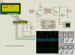
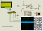
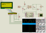
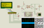
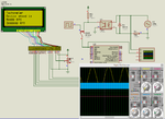
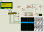
hello everyone I am trying to measure frequency using PIC16f886. I am using simple comparator for Sine wave to square wave conversion. And I have attached the input of comparator with RA4/T0CLK to use Timer0 as a counter.I have also copied code for it but my LCD displays counts from 0-9 and then again roll overs to 0 and starts counting again. The code I copied is:
Code:
void Display_Freq(unsigned int freq2write)
{
 frequency[1] = (freq2write/10) + 48;    // Extract tens digit
 frequency[2] =  (freq2write/1)%10 + 48;    // Extract ones digit
 // Display Frequency on LCD
 Lcd_Out(2,13,frequency);
 Lcd_Out(2,15,"Hz");
}

Please guide me.
 

Post full code. I don't have that code. The code you have posted is Rajendra Bhatt's code. I will write a code for you. It seems you are using mikroC and hence I will write mikroC code.
 

I made two frequency counters using PIC16F877A and mikroC PRO PIC Compiler. I have not measured the max frequency that the counters can measure. Do the maths.

The ver1 measured 1000 Hz and ver2 measured 10000 Hz. So, if they are used for tachometer then they can easily measure 60 K RPM and 600000 RPM.

- - - Updated - - -

Change the resistor value from 220K to 270k 1/2W.

- - - Updated - - -

I tested the ver2 and it also measured 50 KHz exactly. So, if it is used for tachometer then it can measure 3000000 RPM without problems. In proteus it took some 10 seconds to display the data on LCD. Maybe it is simulation problem. Test in hardware and reply.

I will make a frequency counter using STM32 running at 200 MHz. I will see if it can measure MHz and GHz signals.


Edit: Tachometer image attached. Please somebody test the working in hardware. I don't have a signal generator.

- - - Updated - - -

Proteus took 20 seconds to display data on LCD. See last image.
 

Attachments

  • Frequency Counter rev1.rar
    184.1 KB · Views: 46
  • Freq Counter ver2.rar
    219.2 KB · Views: 43
  • frequency_counter.png
    frequency_counter.png
    141.5 KB · Views: 66
  • freq counter ver2.png
    freq counter ver2.png
    169.8 KB · Views: 65
  • freq counter ver2 a.png
    freq counter ver2 a.png
    141.1 KB · Views: 72
  • tachometer.png
    tachometer.png
    117.4 KB · Views: 60
  • tachometer 2.png
    tachometer 2.png
    140.4 KB · Views: 64
Last edited:

Frequency counter version 5 which uses T1CKI. It is not precise. For 50000 Hz it shows some 49973 Hz. Proteus took 25 seconds to display data on LCD. Proteus time was running very slow. I know its because Proteus has to simulate a lot of things. I have ordered 50 MHz signal generator. I will test in hardware and reply soon.
 

Attachments

  • freq counter.png
    freq counter.png
    135.5 KB · Views: 62
  • Freq Counter ver5.rar
    172.8 KB · Views: 47

The data is displayed on LCD every 1 sec. It displays properly on hardware. Just in Proteus if frequency input is high Proteus time will be slow like to simulate 1 second actual time Proteus takes 20 to 30 seconds.
 

Status
Not open for further replies.

Part and Inventory Search

Welcome to EDABoard.com

Sponsor

Back
Top