canarybird33
Member level 1

- Joined
- Apr 16, 2013
- Messages
- 41
- Helped
- 2
- Reputation
- 4
- Reaction score
- 2
- Trophy points
- 1,288
- Location
- Mashhad, Iran, Iran
- Activity points
- 1,591
Hi every body
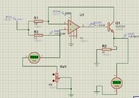
I want design a circuit to measure load current(LOW COST and reliable)
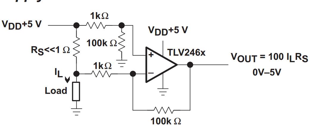
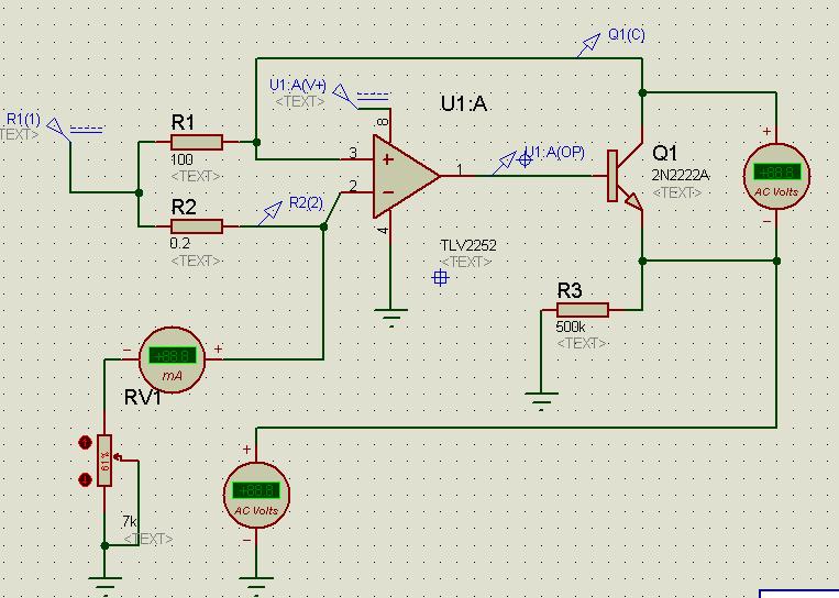
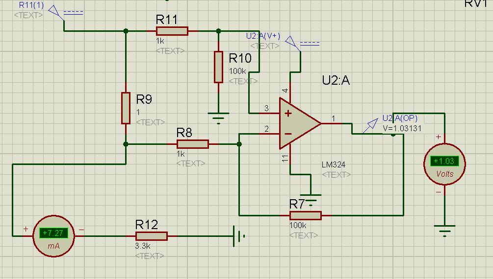
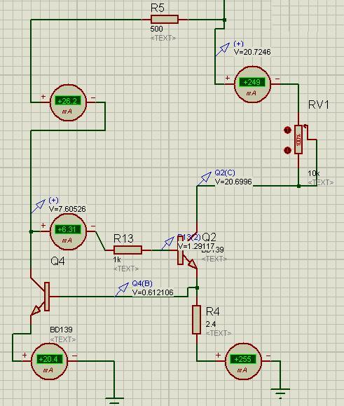
I chose the blow circuit but it doesn't work
(changing the load current doesn't cause voltage variation in a range)
How can I correct this circuit.
load current variation is 3mA to 300 mA and I want to convert it to 0V to 5 ( and the use the ADC of micro-controller)
I want design a circuit to measure load current(LOW COST and reliable)
I chose the blow circuit but it doesn't work
(changing the load current doesn't cause voltage variation in a range)
How can I correct this circuit.
load current variation is 3mA to 300 mA and I want to convert it to 0V to 5 ( and the use the ADC of micro-controller)