Continue to Site

Welcome to EDAboard.com

Welcome to our site! EDAboard.com is an international Electronics Discussion Forum focused on EDA software, circuits, schematics, books, theory, papers, asic, pld, 8051, DSP, Network, RF, Analog Design, PCB, Service Manuals... and a whole lot more! To participate you need to register. Registration is free. Click here to register now.

[SOLVED] Measuring inductance in simulation

Status
Not open for further replies.

MobiNaz

Full Member level 3
Joined
Aug 11, 2010
Messages
163
Helped
5
Reputation
10
Reaction score
4
Trophy points
1,298
Location
SYDNEY
Activity points
2,432
Hi all,

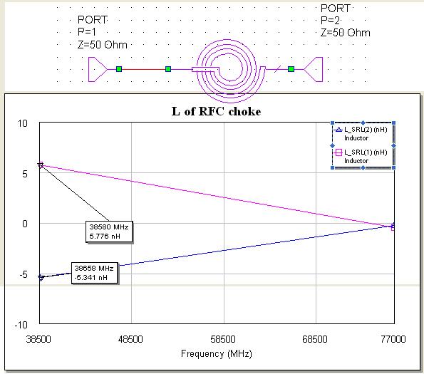
I want to measure the inductance of planar spiral in simulation by MWO. I am currently using L_SRL function in MWO office and getting positive and negative inductances for the two ports. What does it mean?

Which port inductance is the actual one? In the figure attached they are both same in magnitude but they can be varied by changing dimensions.

Thanks in advance


Your test setup is wrong..
The coils shouldn't be tested as you have done..
One port must be grounded, the other port is used to get z-parameters..
Then you should compute that..

\[L=\frac{Im{{Z}_{11}}}{2.\pi .freq}\]

\[Q=\frac{Im{Z}_{11}}{Re{Z}_{11}}\]
 
Of course one port should be grounded. And for better accuracy, you can copy the shape of the inductor from the layout and place it in the AWR EM simulator (and set all the other parameters), and find the L_SRL after the EM simulation.
 
I do not know the equation used in the L_SRL calculation.

Of course, the inductance can also be extracted from the 2-port setup: L = - imag(1/Y21) / (2*pi*freq)
 

Thanks everyone, but one question how do we measure the inductance of a stub in MWO.


Vfone: How do I copy schematic into EM. Can you help if I mail you the schematic ?

Thanks in advance
 

Status
Not open for further replies.

Similar threads

Part and Inventory Search

Welcome to EDABoard.com

Sponsor

Back
Top